

While we can deliver a pre-wired ’62 Jazz Bass control assembly, if you want to save some money and wire it yourself using this kit, you can.
Pictured below: The kit itself.
What’s in the kit:
- American Vintage ’62 Jazz Bass 3-hole control plate with 3 chrome screws.
- 2x: American Vintage ’62 Jazz Bass CTS concentric 250/500K solid shaft potentiometers
- 2x: American Vintage ’62 Jazz Bass upper control knob
- 2x: American Vintage ’62 Jazz Bass lower control knob
- 2x: American Vintage ’62 Jazz Bass detent spring plate
- Switchcraft Mono Jack
- .047Mfd Orange Drop Capacitor
- .033Mfd Orange Drop Capacitor
- Vintage Style Cloth Covered Wire Set, 3.5″ Black & 3.5″ White, Vintage Style push back, cloth covered wire, 22 gauge, Unshielded, single conductor, stranded wire with a waxed braided cotton outer insulation.

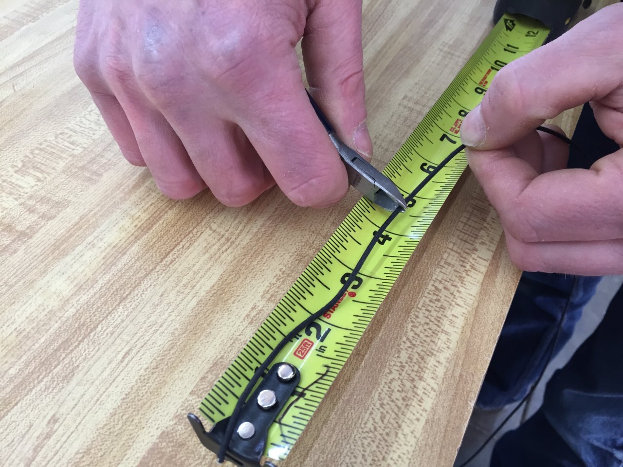
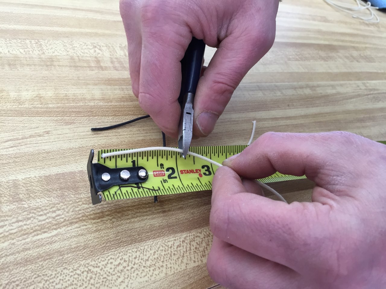
Below: Cutting 4 pieces of wire, 2 black and 2 white. The 2 black wires were cut to 4.25″ and 3.5″, the two white wires were cut to 4.5″ and 2.0″.
Below: Since this is push-back cloth wiring, the insulation is not rigidly stuck. THis requires taking a little more time to expose the end compared to PVC style wiring.
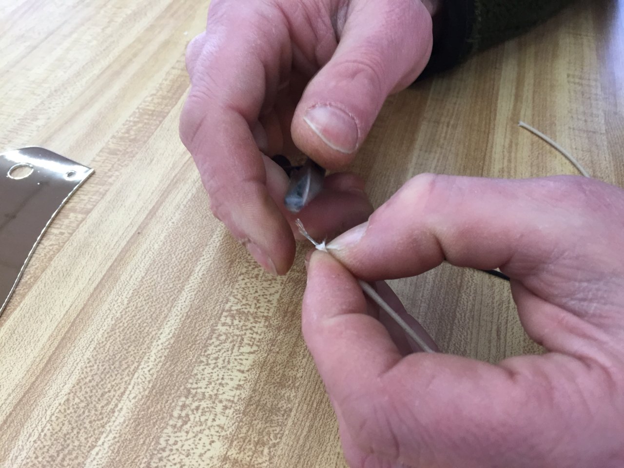
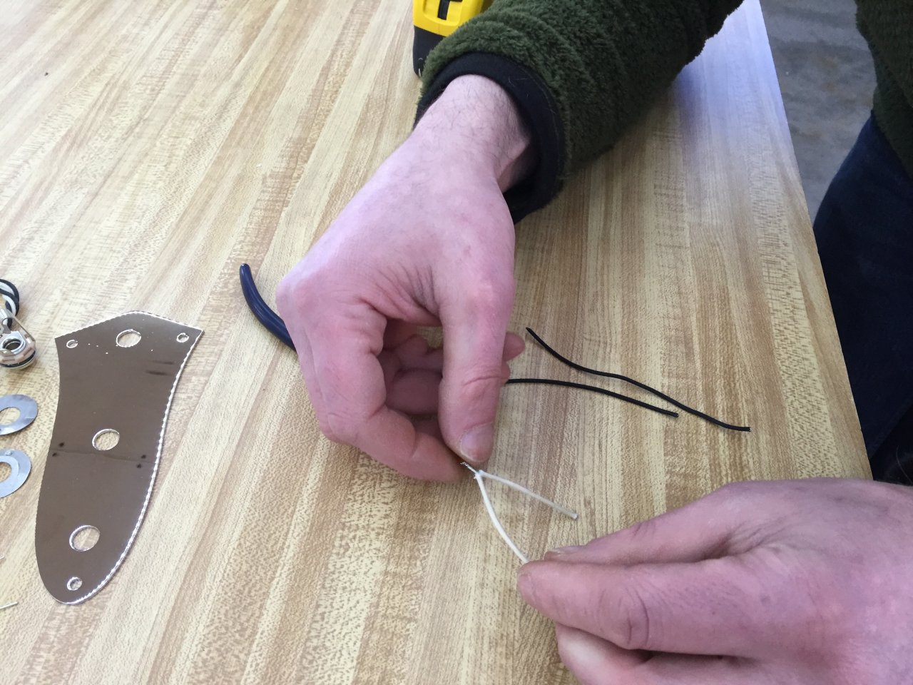
Below: Two cut pieces of white wire, both with exposed ends, twisting the two together to make a joined “Y” piece.
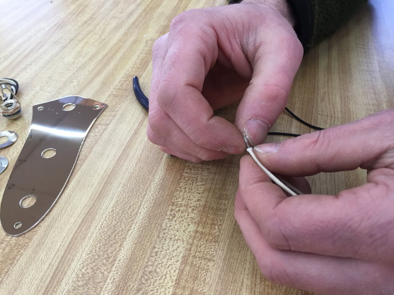
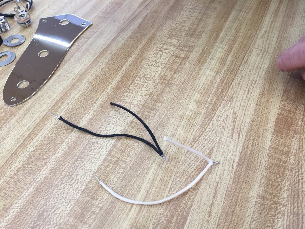
Below: The same has been done with the black wire, the white wire and black wire pieces have been both joined to make their respective “Y” pieces.
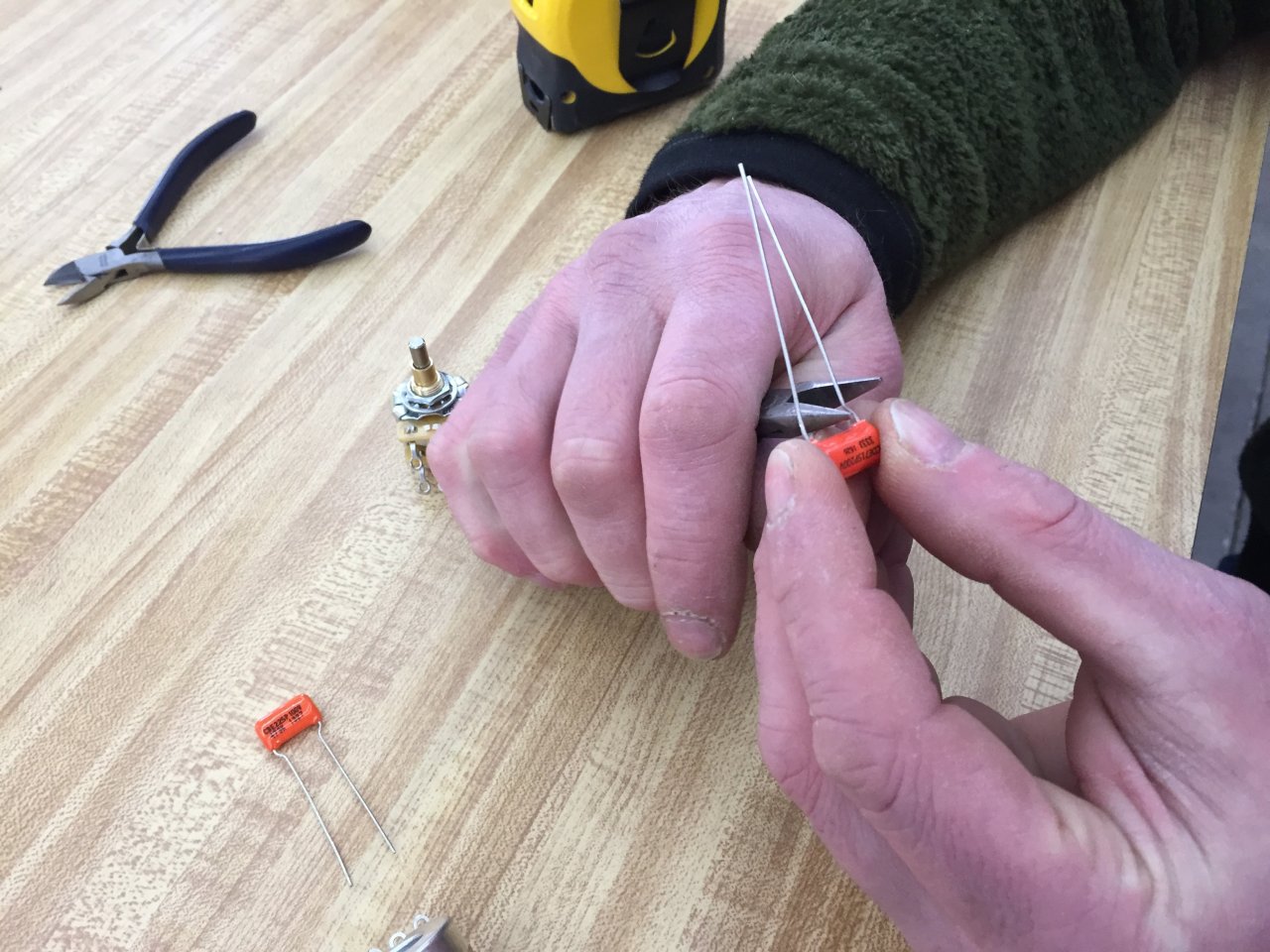
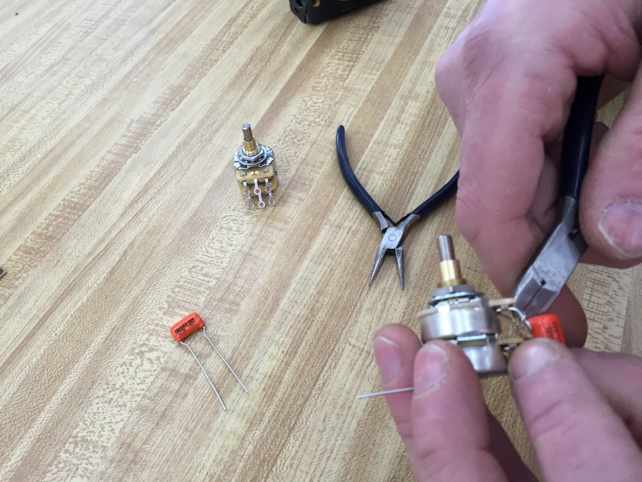
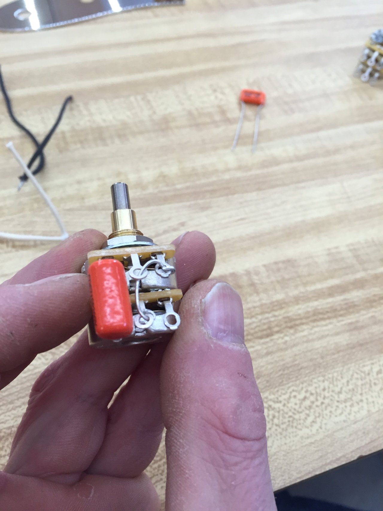
Below: Both orange caps are manufactured with small bends directly after the cap. Pliers are being used to reshape the leads to be straight.
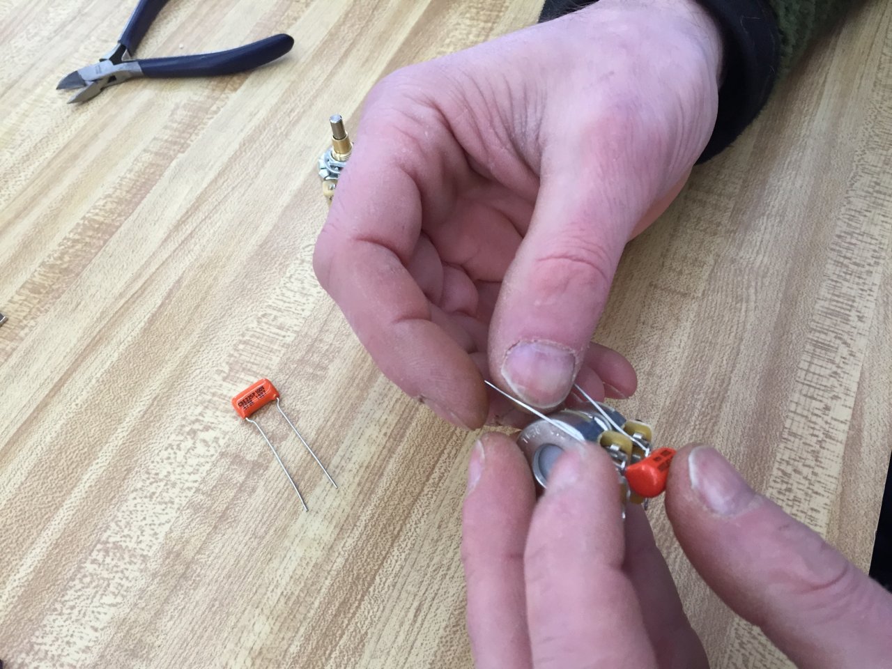
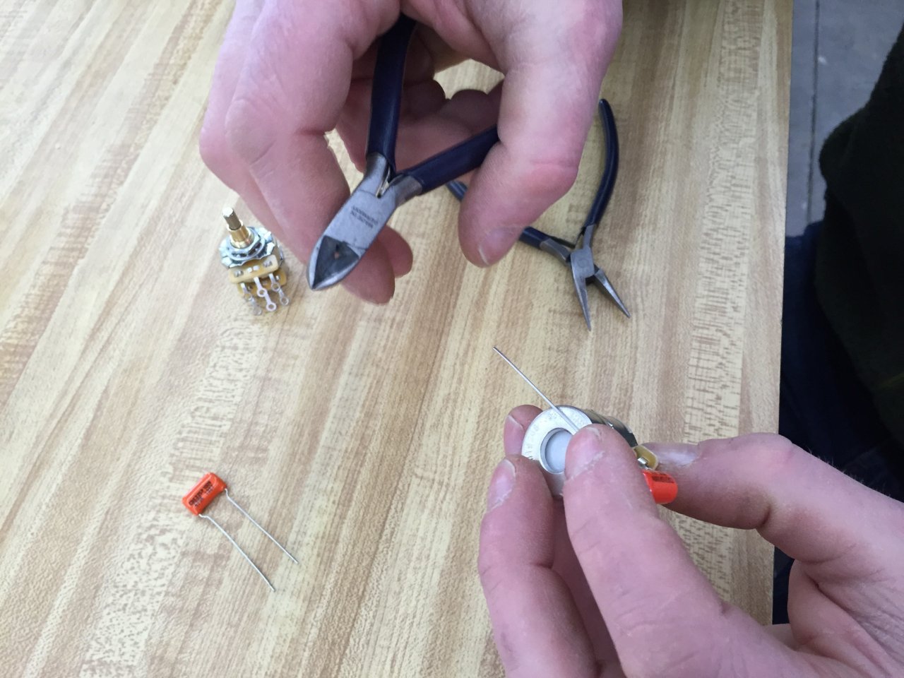
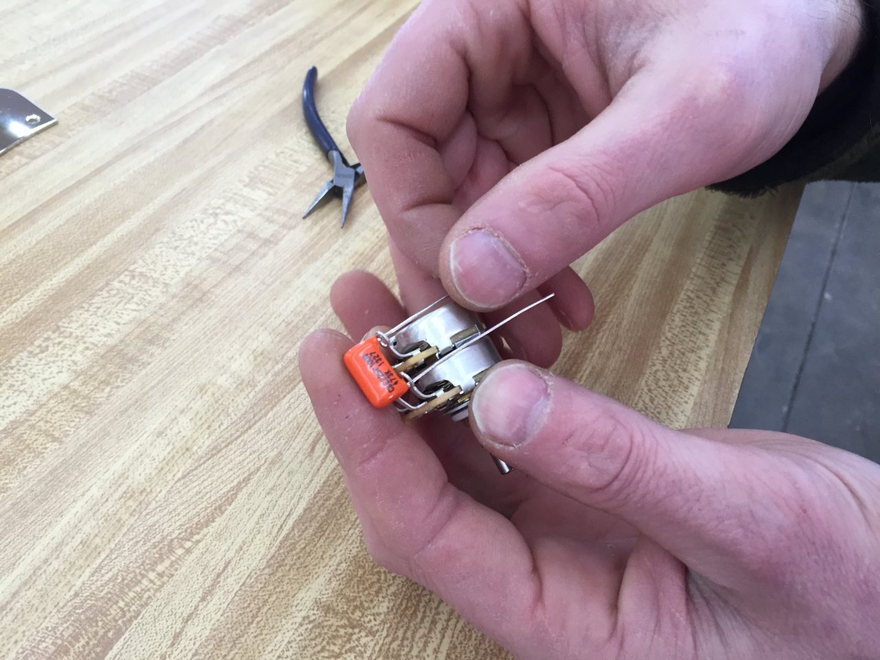
Below: The straight leads have been pushed through the loop ends on both upper and lower decks on the right hand side terminals.
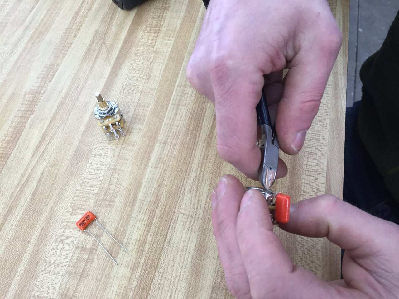
Below: Lead on the lower terminal has been wrapped around and the excess is being cut off.
Below: About to cut off the excess of the upper lead, with enough excess left so it can be soldered to the potentiometer.
Below: Lead has been clipped.
Below: Taking one of the potentiometer clipped leads (from the capacitor), pushed down through the loop ends of the two center tabs, then bent over and thorugh the loop end of the lower left terminal, acting as a jumper.
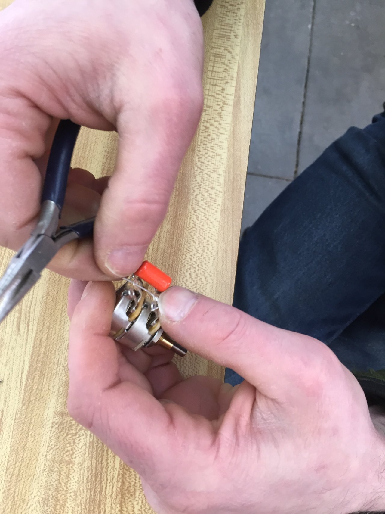
Below: The jumper that goes between the 3 terminals has been installed. Note that no soldering has taken place at this point.
Below: This is the .047Mfd capacitor (for neck side pickup). The procedure for wiring this is identical to the .033Mfd.
Below: Mechanical prep work is done.


This is wiring is incorrect; you need two 220k resistors to isolate the two sets of controls from each other, otherwise what’s the point of having two tone controls, because turning down one will affect both pickups. But there’s also the problem with this setup, and why Fender (and even Jaco) stopped using it; it darkens the tone too much due to the extra resistance from the extra tone control, and the needed series resistors.
This wiring is not incorrect. It is one of the two wireings that Fender used in the sixties. It is also not true that this causes any problems. It may sound different as the VVT wireing but different does not mean wrong. In fact there are bassists that prefer the tone this wireing gives over the more modern wireing and it sure offers a wider range of tone option as the standard setup. Why Fender changed it is not documented but one possible reason could be that this wiring is more expensive than the VVT version.