
This is a continuation from part 2.
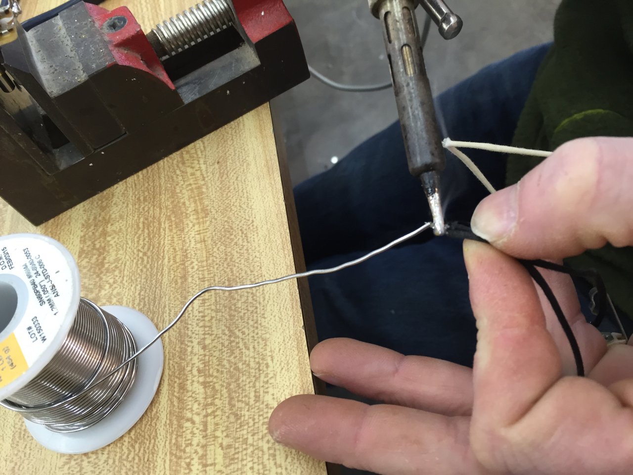
Below: Tinning the ground wire in preparation for soldering (the white wire later also will be tinned).

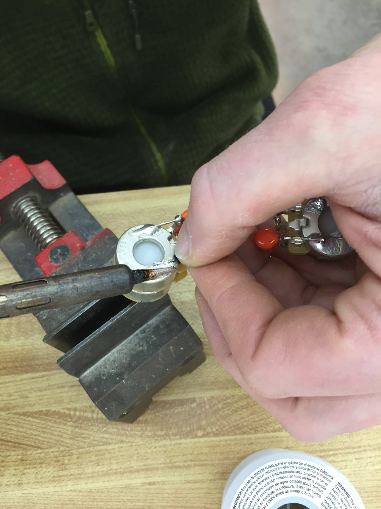
Below: Soldering the ground wire to the pot.
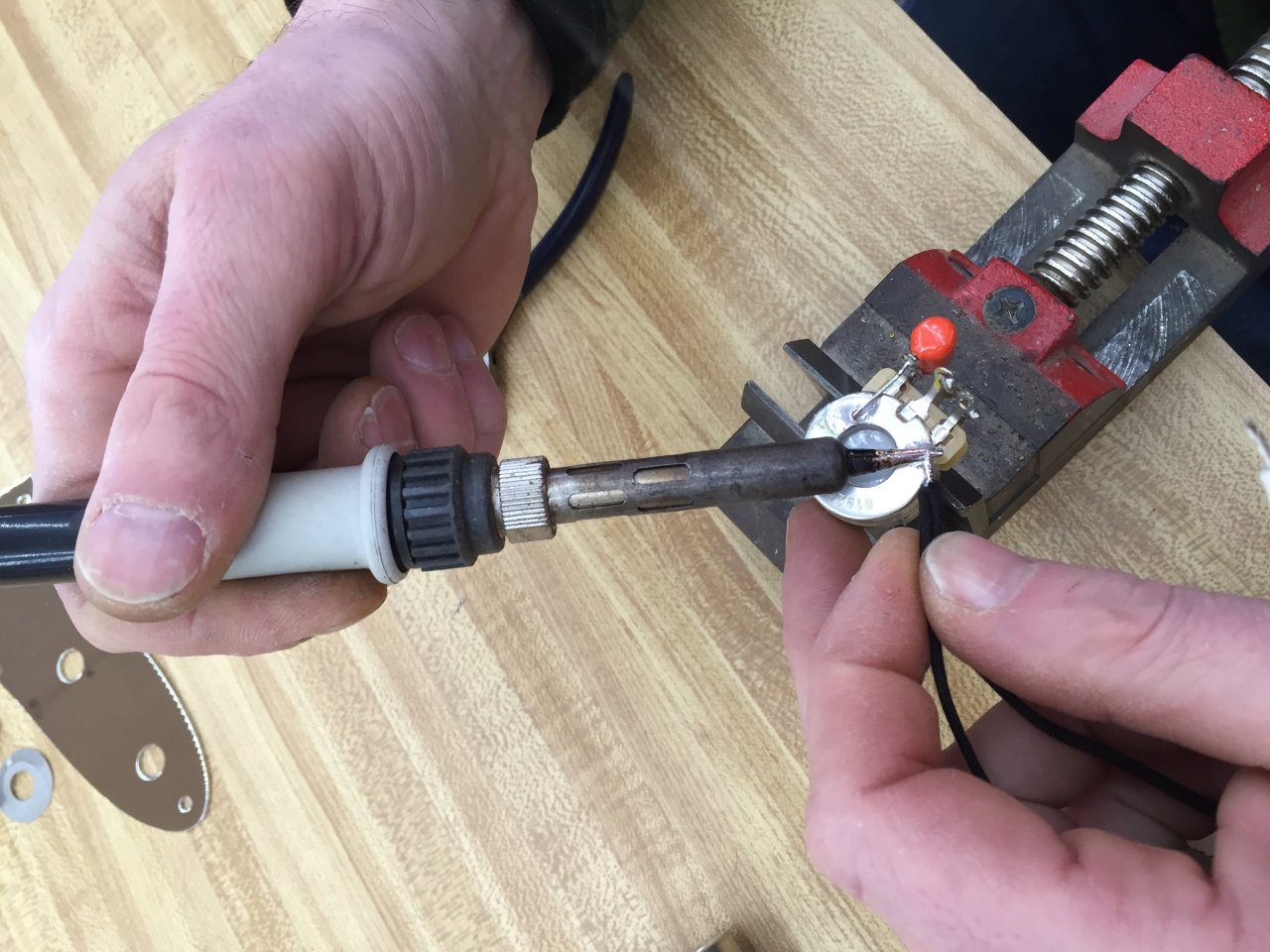
Below: Soldering the white wire to the upper left terminal.

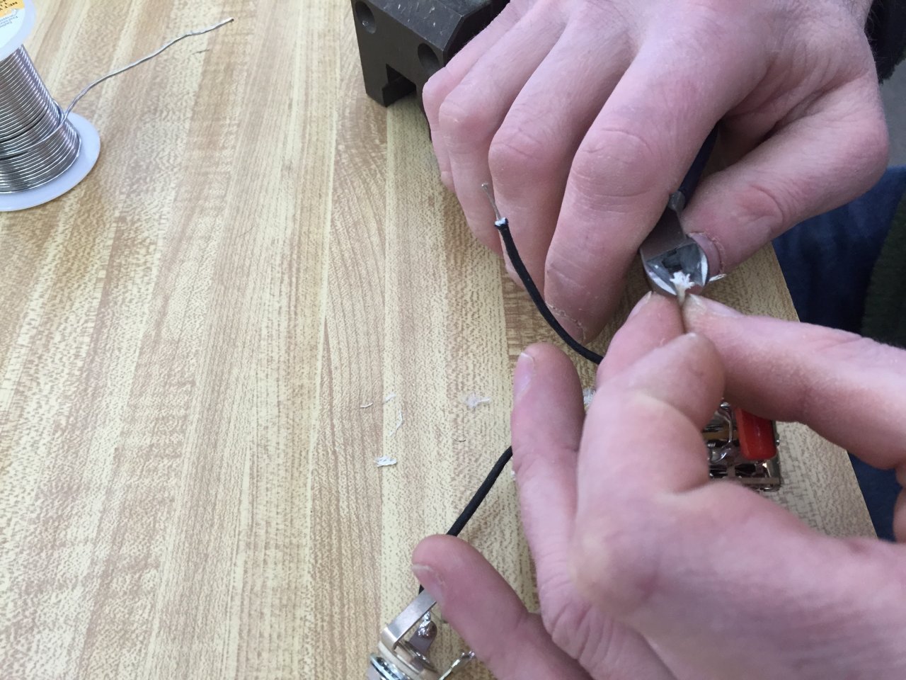
Below: Coaxing the wire out of the ends of the cloth coating.
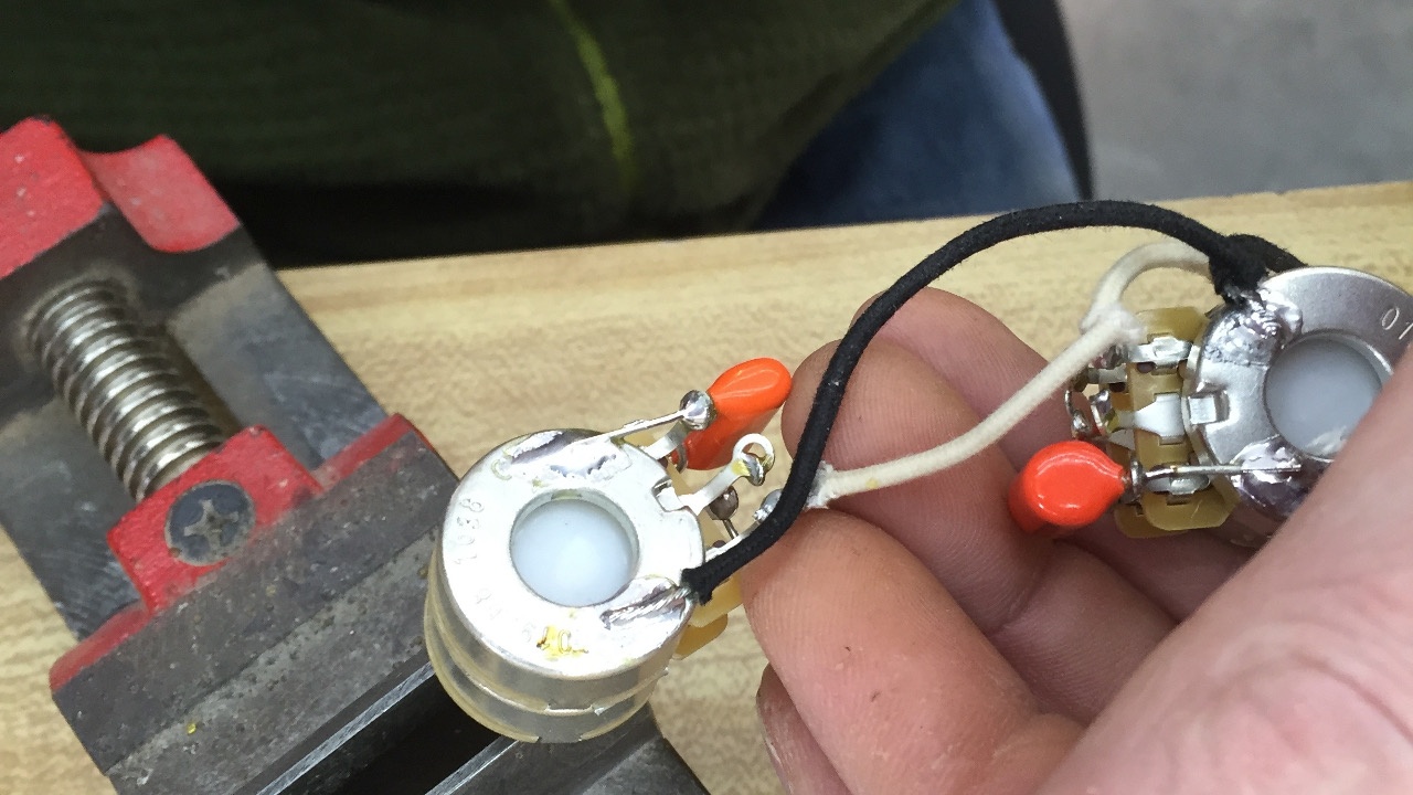
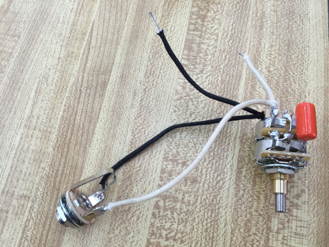
Below: Progress thus far. Potentiometer and output jack are connected.
Below: Potentiometer for the neck pickup.

Below: Tinning the end of the white signal wire for the neck pickup potentiometer.

Below: After white signal wire has been soldered, black wire is tinned and soldered to the potetiometer.
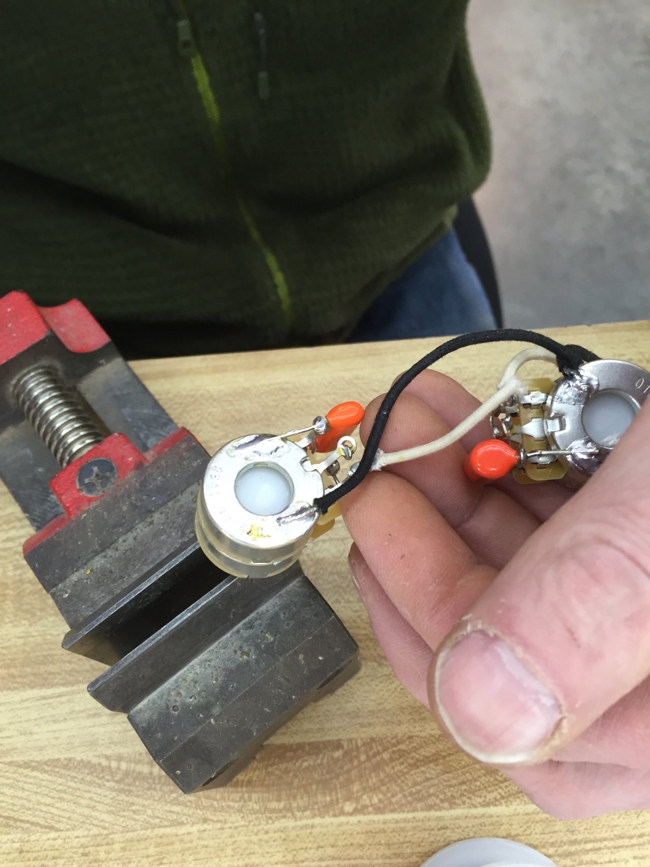
Below: Completed soldering for neck pickup potentiometer. All soldering is completed at this point.
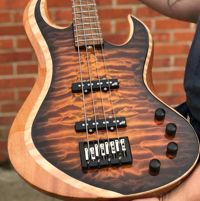

I thought the originals had a pair of resistors (220K?) coming from the output of both pots, so there wasn’t any interaction between the two sets of vol/tone. This way you could wind the tone all the way down on one pickup (for example) without it affecting the other pickup. Way more versatile. The downside being you had less output and clarity, due to the ‘mix’ resistors.
Adding resistors does make blending the pickups better, but they take the bite out your pickups. My bass sounded way punchier without them.