ACG Bass Preamp Wiring Diagrams
ACG bass preamp wiring as text: the EQ-02 screw-terminal pre-amp and the discontinued Bass-EQ-01 filter preamp, with ACG's connection keys written out terminal by terminal.
Before you start
- ACG preamps take pickup hot and cold on separate terminals; keep them the right way round.
- The orange lead is the output to the jack tip and the green lead is ground.
On this page
ACG EQ-02 pre-amp
The EQ-02 needs no soldering: every connection is a screw terminal. The main board is common to all configurations, and the filter stack connection is duplicated on the back of the board.
Written from ACG's own EQ-02 installation sheet (our old PDF link was broken). For single-pickup versions, use the neck inputs and neck gain only.
| Gain trims | Terminal 5: neck pickup gain, 0 to +12 dB (the only one used on single-pickup versions). Terminal 6: bridge pickup gain, 0 to +12 dB |
|---|---|
| Internal pot marked red | Not user adjustable; ACG says moving it voids the warranty |
| Passive tone | Wires into the pickup inputs with a 3-wire ribbon cable |
| Flexi-strips | They bend, but ACG says to keep bending to a minimum |
| Power | 9 V or 18 V |
| # | From | To | Notes |
|---|---|---|---|
| 1 | Neck pickup cold (−) | Main board terminal 1 | Use for single-pickup versions |
| 2 | Neck pickup hot (+) | Terminal 2 | Use for single-pickup versions |
| 3 | Bridge pickup cold (−) | Terminal 3 | Not used on single-pickup versions |
| 4 | Bridge pickup hot (+) | Terminal 4 | Not used on single-pickup versions |
| 5 | Battery clip + (red) | Terminal 7 | |
| 6 | Output (orange) | Jack tip | From terminal 8 |
| 7 | Ground (green) | Jack ground | From terminal 9 |
Step by step
- Mount the stacks and board. Keep bends in the flexi-strips to a minimum.
- Neck pickup cold to terminal 1, hot to terminal 2; bridge pickup cold to 3, hot to 4.
- Battery clip red to terminal 7. Orange output to the jack tip, green ground to the jack ground.
- Connect the passive tone ribbon to the pickup inputs.
- Set the neck and bridge gain trims (5, 6) to balance the pickups. Leave the red-marked internal pot alone.
See also
ACG Bass-EQ-01 filter-style pre-amp
Four stacked knobs, built around a low-pass filter for each pickup rather than the usual cut/boost EQ.
The EQ-01 is discontinued at Best Bass Gear. For a current ACG-style filter preamp, see our ACG preamps page.
| Volume / Blend stack | Upper ring volume; lower ring blend (anti-clockwise bridge, clockwise neck, centre click equal mix) |
|---|---|
| Bridge filter stack | Lower ring filter frequency (low-pass, up to about 3 kHz); upper ring filter peak (resonance boost) |
| Neck filter stack | Same as the bridge stack |
| Treble stack | Lower ring treble frequency (high-pass, down to about 1 kHz); upper ring treble level |
| Internal trims | Pickup gain on each filter board (shipped at minimum); treble-feed blend on the main board (set to the bridge pickup) |
| # | From | To | Notes |
|---|---|---|---|
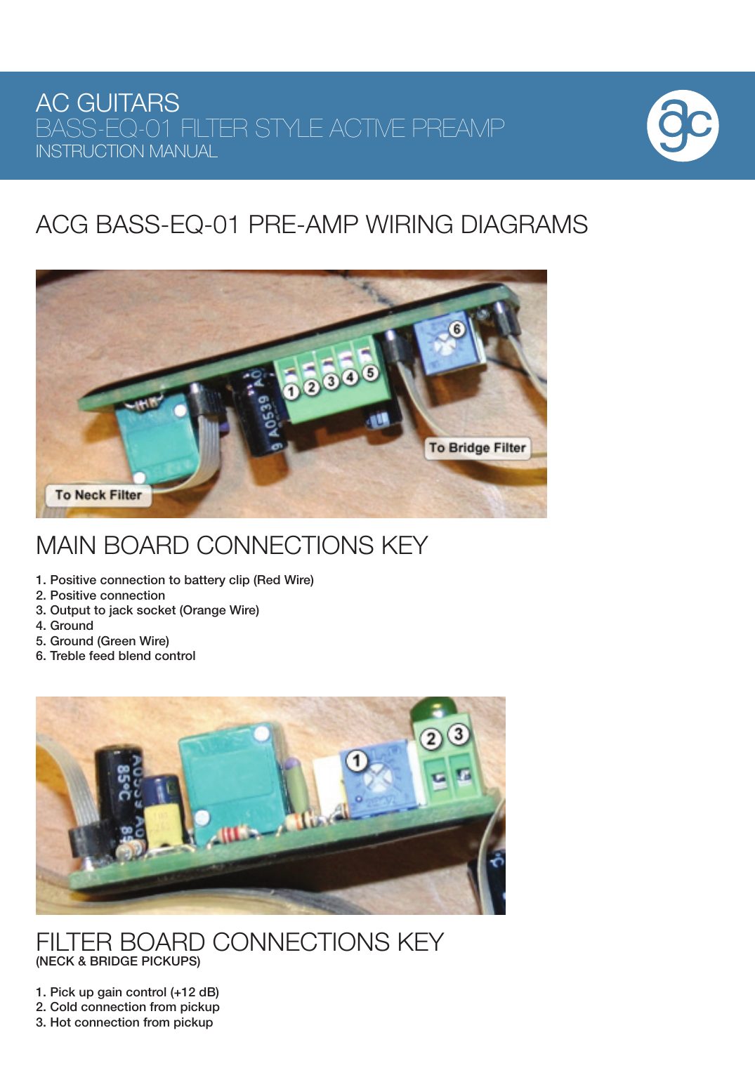
| 1 | Battery clip red | Main board 1 | Positive |
| 2 | — | Main board 2 | Positive connection |
| 3 | Output (orange) | Jack tip | From main board 3 |
| 4 | — | Main board 4 | Ground |
| 5 | Ground (green) | Jack ground | From main board 5 |
| 6 | — | Main board 6 | Treble feed blend control |
| 7 | Pickup cold | Filter board 2 | Each pickup on its own filter board |
| 8 | Pickup hot | Filter board 3 | |
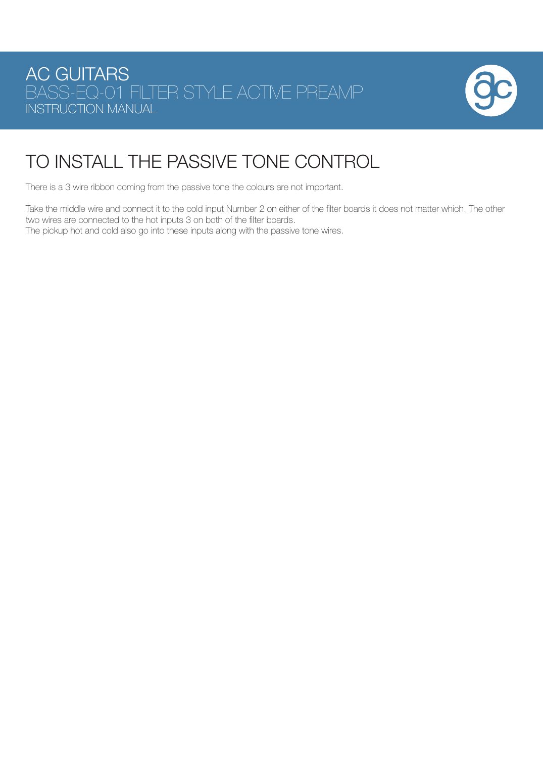
| 9 | Passive tone ribbon, middle wire | Cold input 2 on either filter board | Ribbon colours don't matter |
| 10 | Passive tone ribbon, outer two wires | Hot input 3 on each filter board | Shares the terminal with the pickup hot |
FAQ
Do I need to solder an ACG EQ-02?
No. ACG says every connection is made with screw terminals.
How do I wire an ACG preamp with one pickup?
On the EQ-02, use the neck pickup inputs (terminals 1 and 2) and the neck gain trim (5). The bridge inputs and bridge gain are not used.
How does the ACG passive tone connect?
With a 3-wire ribbon into the pickup inputs. On the EQ-01, ACG says the middle wire goes to cold input 2 on either filter board and the outer two to the hot inputs 3, one on each filter board.