Delano Bass Wiring Diagrams
Delano pickup and Sonar preamp wiring as text, from Delano's installation guide and Sonar sheet: pickup mounting, 2- and 4-conductor pickup wiring with series/parallel switching, TheHybrid, Sonar 2/3, 3 MS and Xpure.
Before you start
- Delano shielded 2-conductor colours: white hot, black ground, grey shield.
- Delano 4-conductor colours: white, green, brown, yellow plus ground.
- Delano recommends lining the cavity with copper foil.
- Busy switch drawings are marked FUNCTION-LEVEL: follow the drawing for those lugs.
On this page
- Mounting Delano two-section pickups
- 2-conductor cable (vintage pickups, passive)
- Shielded 1-conductor cable
- Shielded 2-conductor cable, with series option
- 4-conductor cable: series / single coil and series / parallel
- TheHybrid series (J single coil + Sting Ray-style humbucker)
- Sonar 2 and Sonar 3 band EQ
- Sonar with passive treble cut
- Sonar with two volume pots
- Sonar 3 MS and 3 MS/E (mid select)
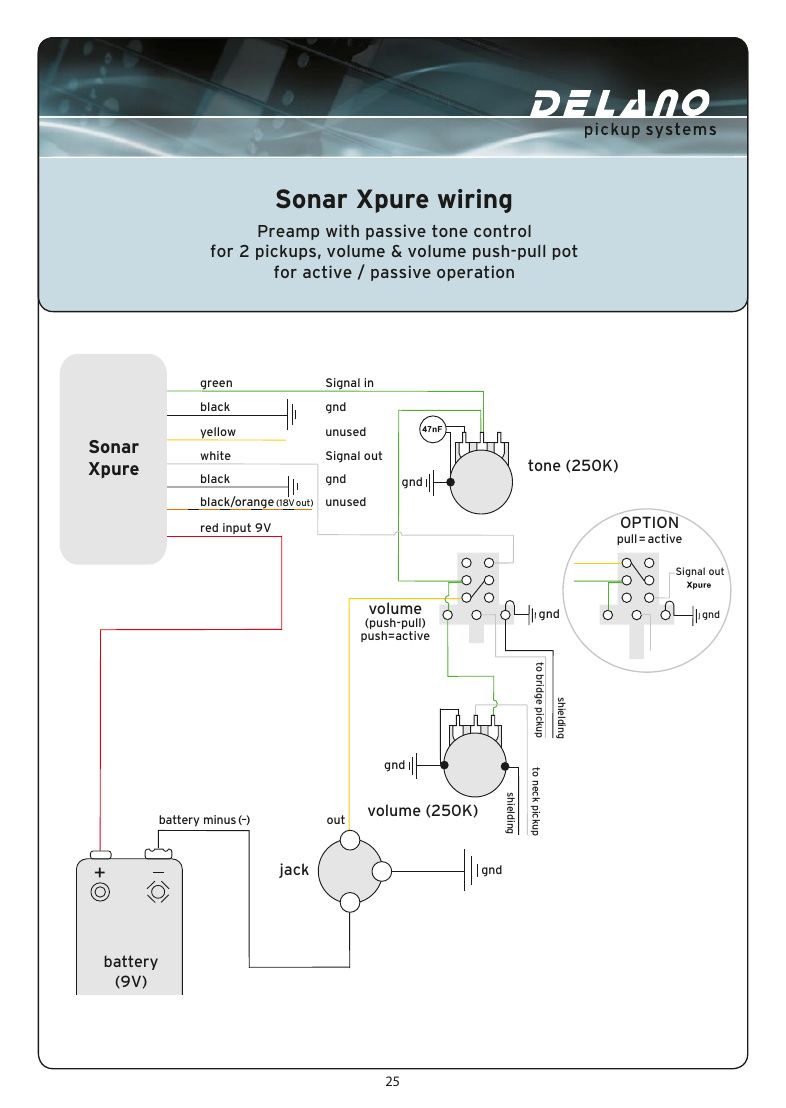
- Sonar Xpure
Delano pickups
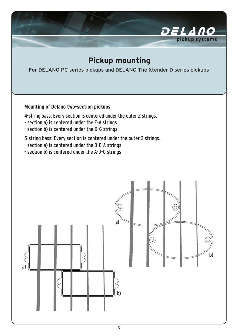
Mounting Delano two-section pickups
For Delano PC series and The Xtender D pickups: each section centres under its outer strings.
| 4-string | Section a) under the E-A strings, section b) under the D-G strings |
|---|---|
| 5-string | Section a) under B-E-A, section b) under A-D-G |
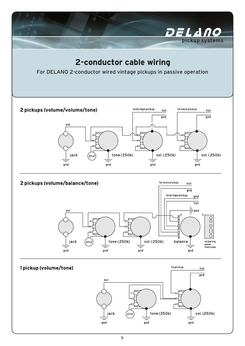
2-conductor cable (vintage pickups, passive)
Hot and ground to your volume, blend or tone controls as drawn.
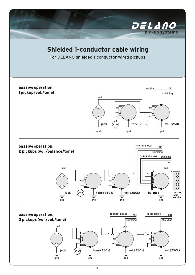
Shielded 1-conductor cable
One hot lead inside a shield. The shield is the ground.
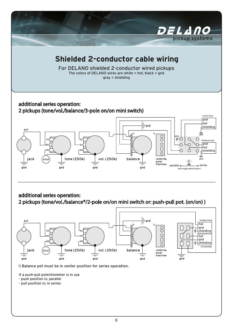
Shielded 2-conductor cable, with series option
Delano colours: white = hot, black = ground, grey = shielding. The sheet adds a series option with a mini switch or push-pull pot.
| Colours | White hot, black ground, grey shield |
|---|---|
| Series switch | 3-pole on/on mini switch, or 2-pole on/on mini switch / push-pull pot |
| Push-pull | Push = parallel, pull = series |
| Balance in series mode | Must be in the centre position (Delano note) |
4-conductor cable: series / single coil and series / parallel
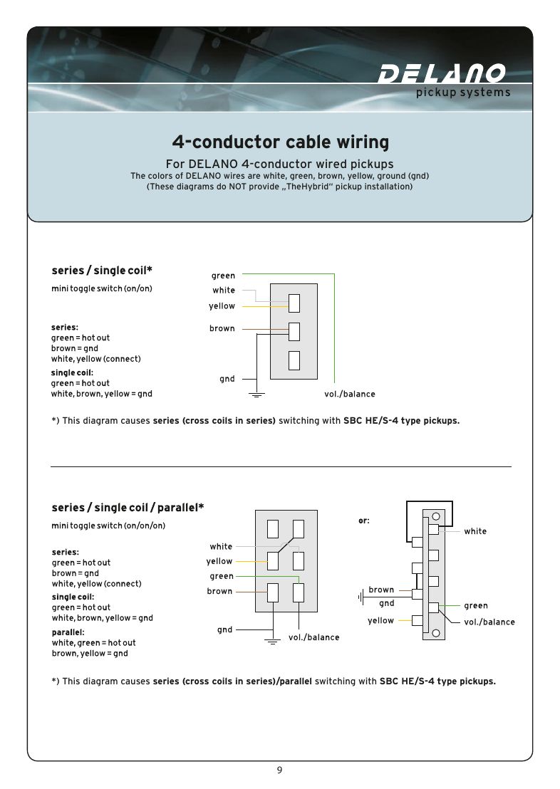
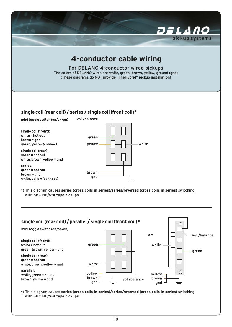
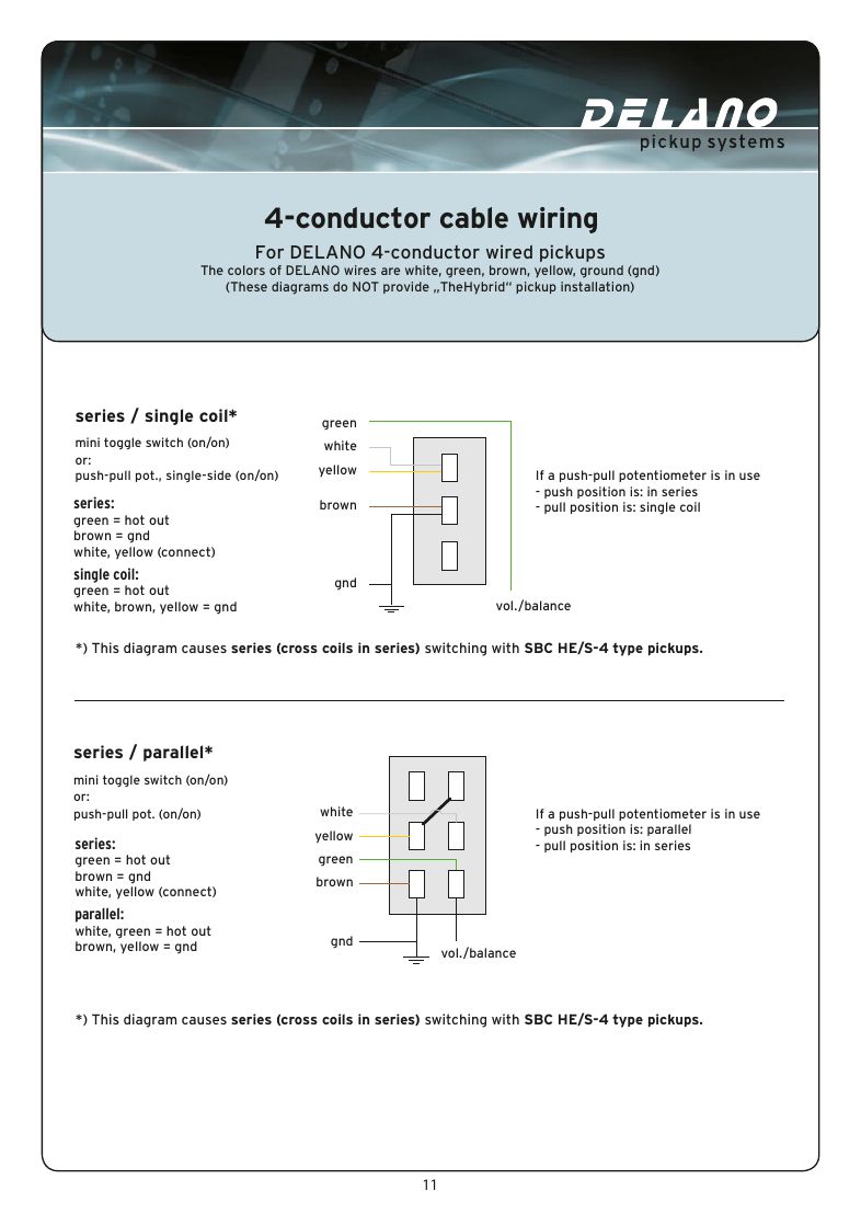
Delano colours: white, green, brown, yellow, plus ground. These diagrams are not for TheHybrid pickups. With SBC HE/S-4 pickups the "series" setting is the cross coils in series.
| Series / single switch | Mini toggle on/on or single-side push-pull: push = series, pull = single coil |
|---|---|
| Series / parallel switch | Mini toggle on/on or push-pull: push = parallel, pull = series |
| Three-way sheet (page 10) | Series / series / reversed (cross coils in series) switching on SBC HE/S-4 pickups |
| # | From | To | Notes |
|---|---|---|---|
| 1 | Series: green | Hot out | |
| 2 | Series: brown | Ground | |
| 3 | Series: white + yellow | Joined together | Not connected to anything else |
| 4 | Single coil: green | Hot out | |
| 5 | Single coil: white, brown, yellow | Ground | |
| 6 | Parallel: white + green | Hot out | |
| 7 | Parallel: brown + yellow | Ground |
See also
TheHybrid series (J single coil + Sting Ray-style humbucker)
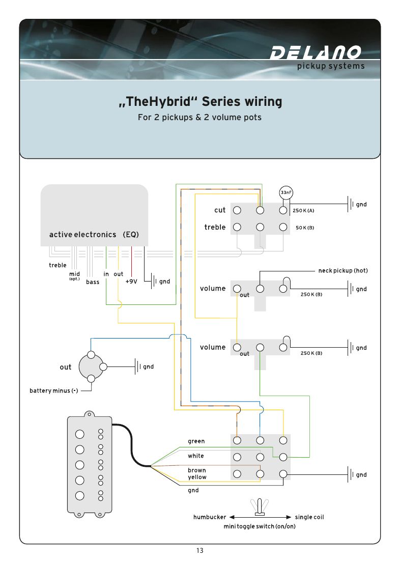
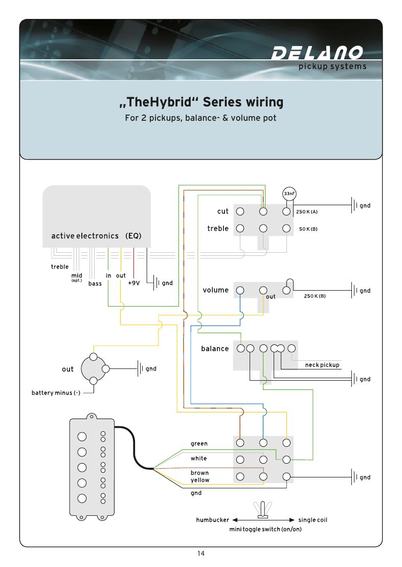
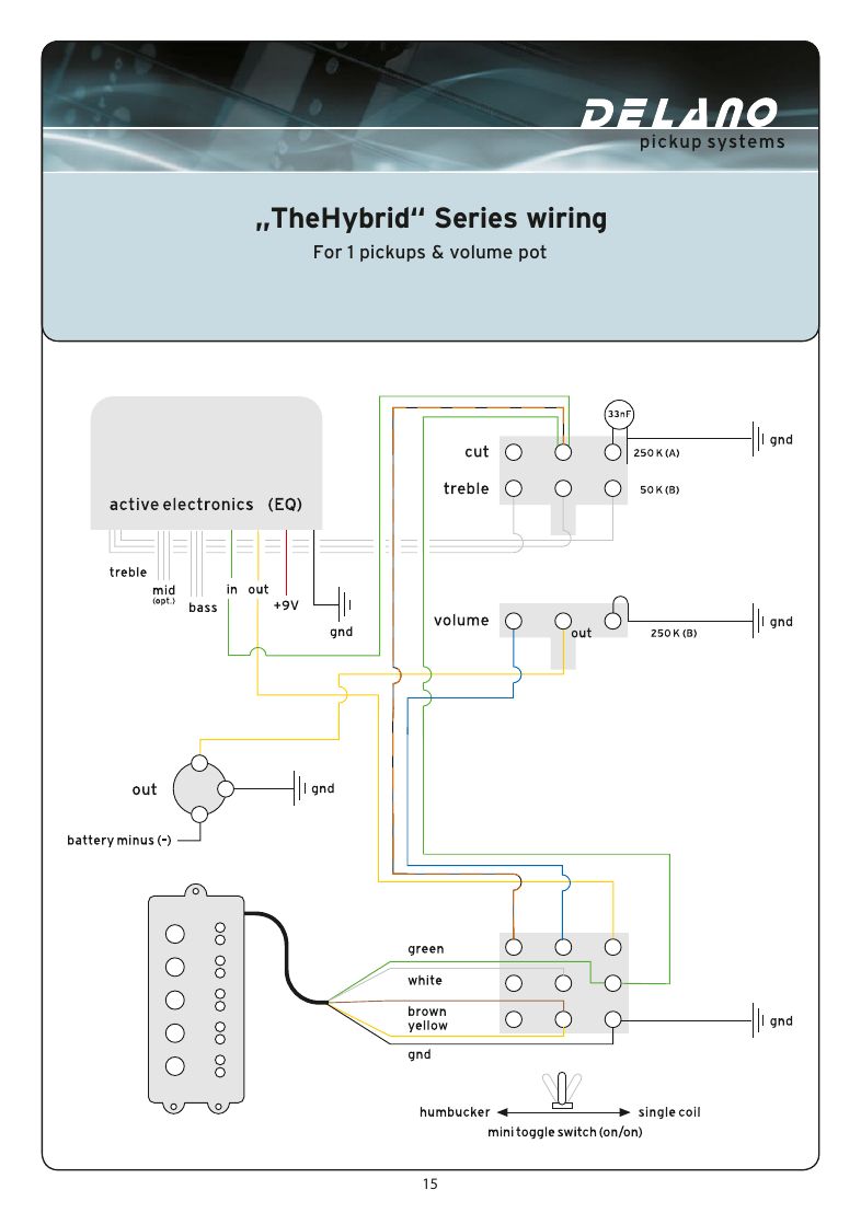
TheHybrid is passive as a J single coil and switches to active 'Ray' humbucker mode with a Sonar 2 or 3-band EQ. Its special treble pot is a passive tone in J mode and the active treble in Ray mode, neutral at centre.
Delano: driving the neck single coil through the active electronics usually hums. For an authentic, hum-free Ray sound, turn the balance fully back to TheHybrid.
FUNCTION-LEVEL: follow the drawing for the switch-manager leads.
| Sheets | Page 13: 2 pickups and 2 volume pots. Page 14: 2 pickups, balance and volume. Page 15: 1 pickup and volume |
|---|---|
| Recommended neck pickup | JC4AL/H or JC5AL/H custom neck J single coil |
Delano Sonar preamps
Sonar 2 and Sonar 3 band EQ
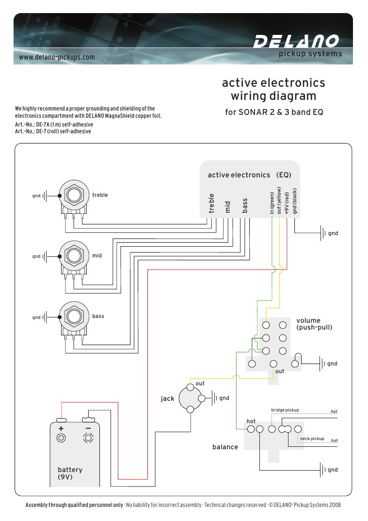
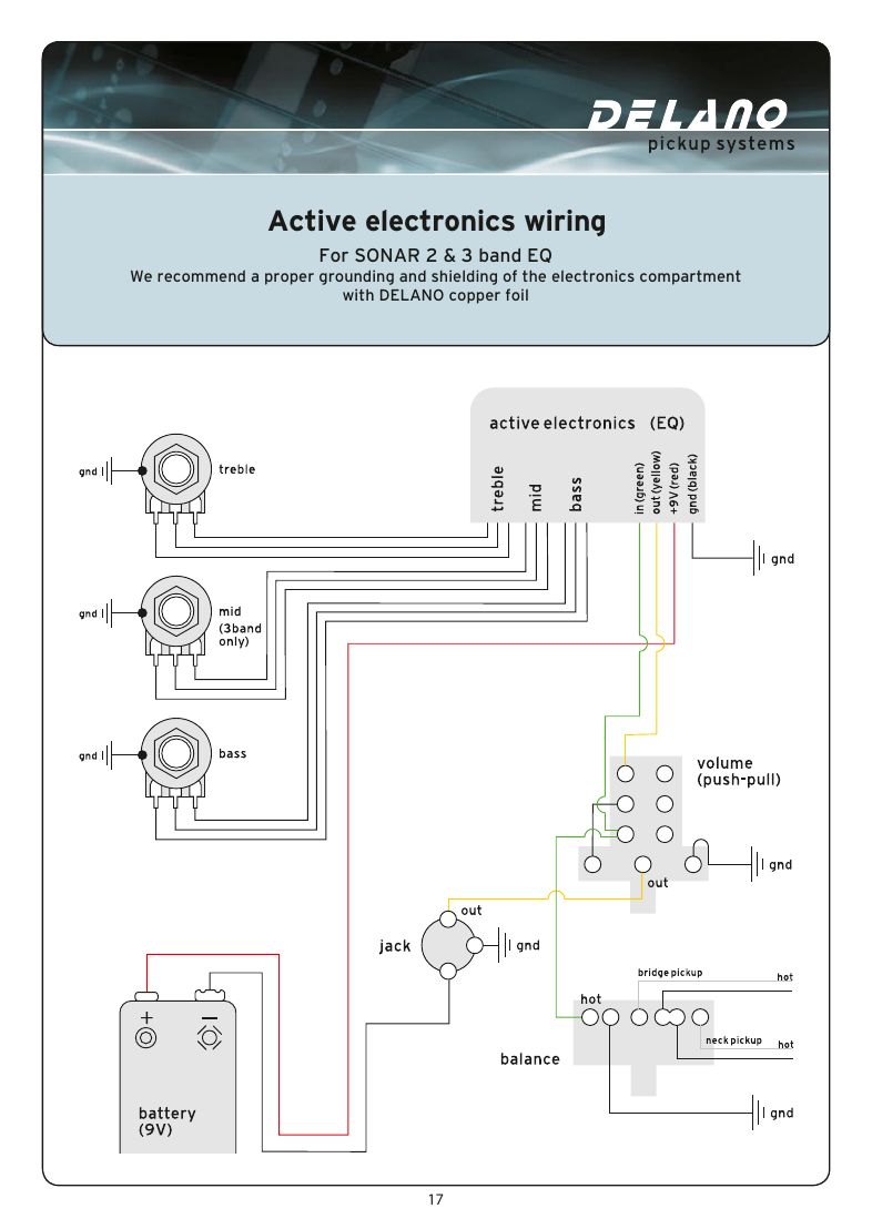
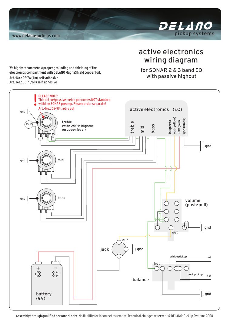
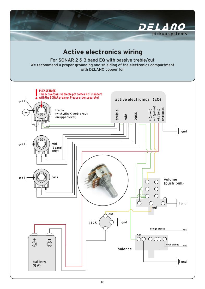
The Sonar is a sealed box with four main leads; each EQ pot connects with grey, green and blue leads. Volume is a push-pull for active/passive.
FUNCTION-LEVEL for the push-pull switch lugs: follow the drawing.
| Shielding | Delano recommends lining the cavity with MagnaShield copper foil (DE-7A 1 m, DE-7 roll) |
|---|
| # | From | To | Notes |
|---|---|---|---|
| 1 | Sonar green | Signal in | From the pickups / balance, as drawn |
| 2 | Sonar yellow | Out (to the push-pull volume) | |
| 3 | Sonar red | +9 V (battery +) | |
| 4 | Sonar black | Ground | |
| 5 | EQ pot leads | Bass, (mid), treble pots | Grey, green and blue to each pot as drawn |
| 6 | Bridge and neck pickup hots | Balance pot |
See also
Sonar with passive treble cut
Same Sonar wiring with a treble pot that has a 250K passive high-cut on its upper level and a 33 nF capacitor.
This active/passive treble pot (DE-9F treble cut) does not come with the Sonar. Order it separately.
Sonar with two volume pots
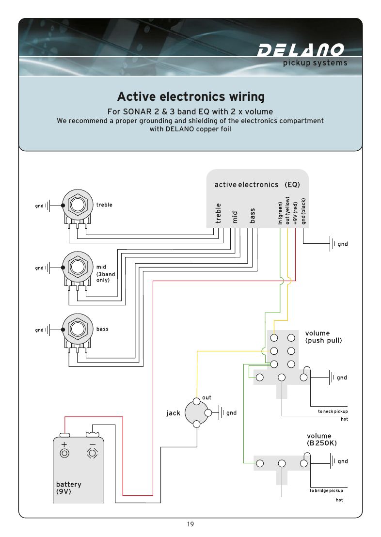
Sonar 2 or 3 with a volume for each pickup instead of volume and balance.
Sonar 3 MS and 3 MS/E (mid select)
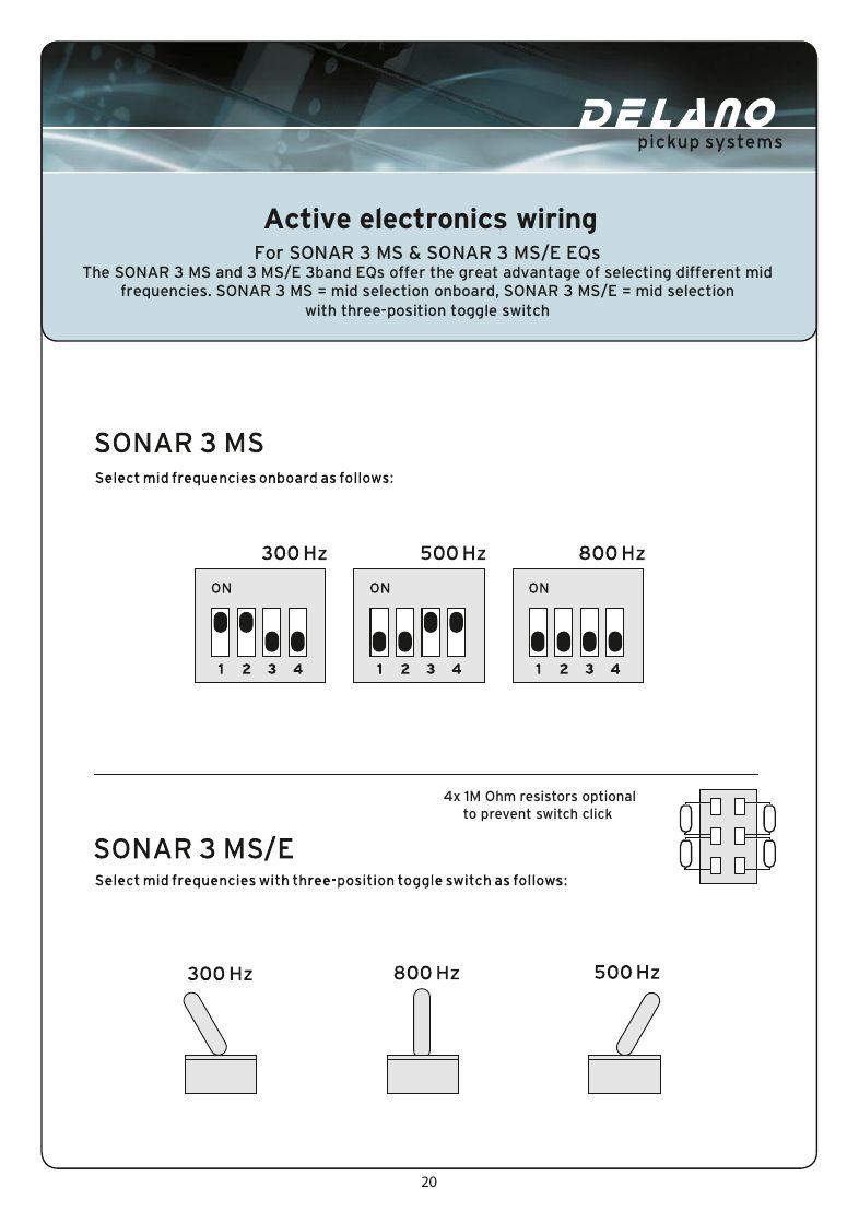
The 3 MS selects the mid frequency onboard; the 3 MS/E uses a three-position toggle. Delano lists four optional 1M resistors to stop the switch clicking.
Sonar Xpure
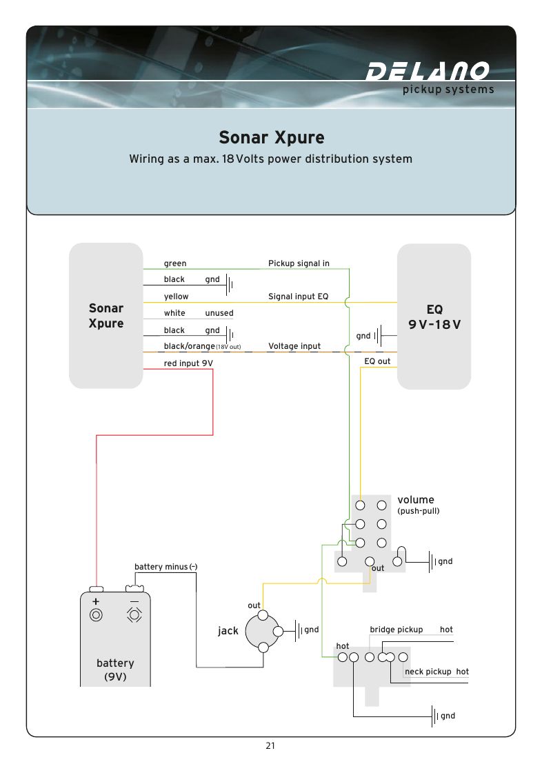
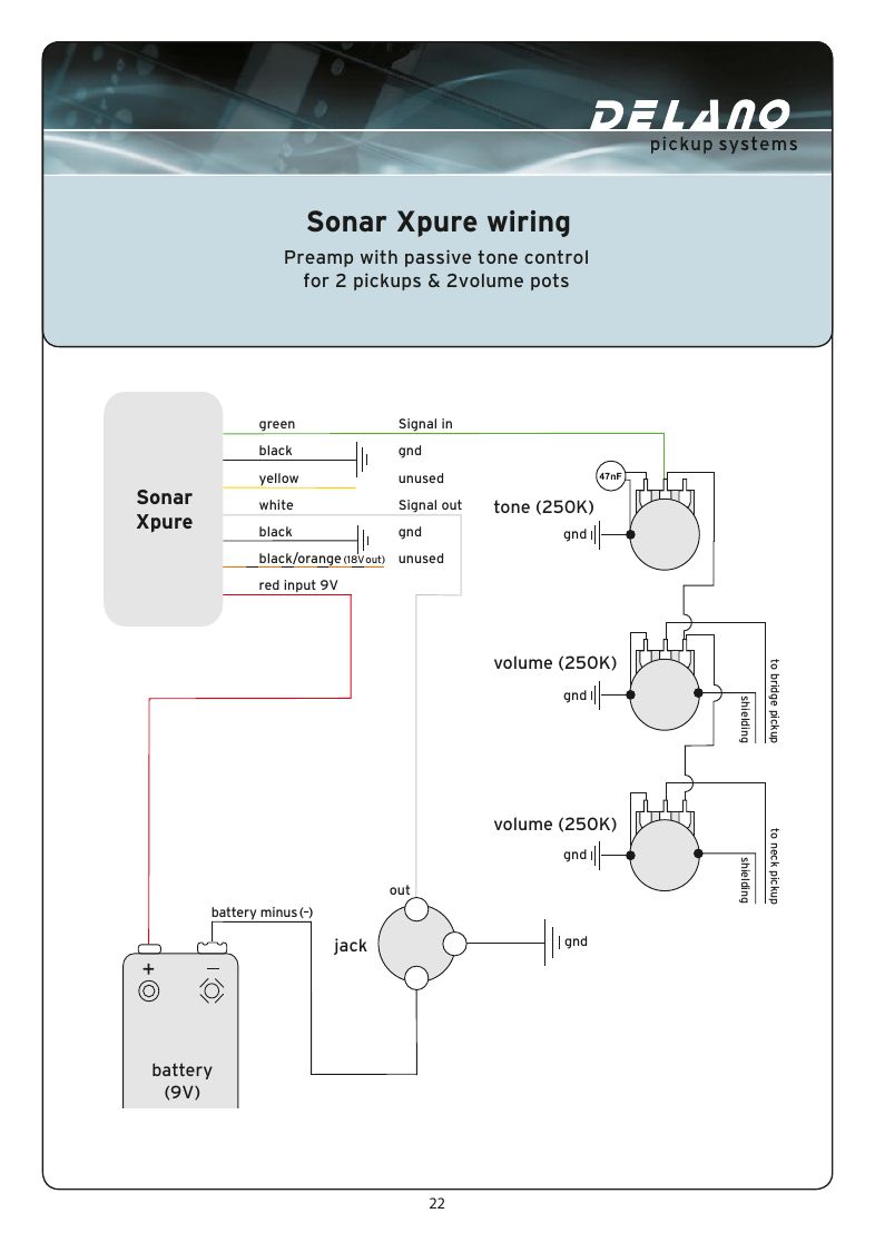
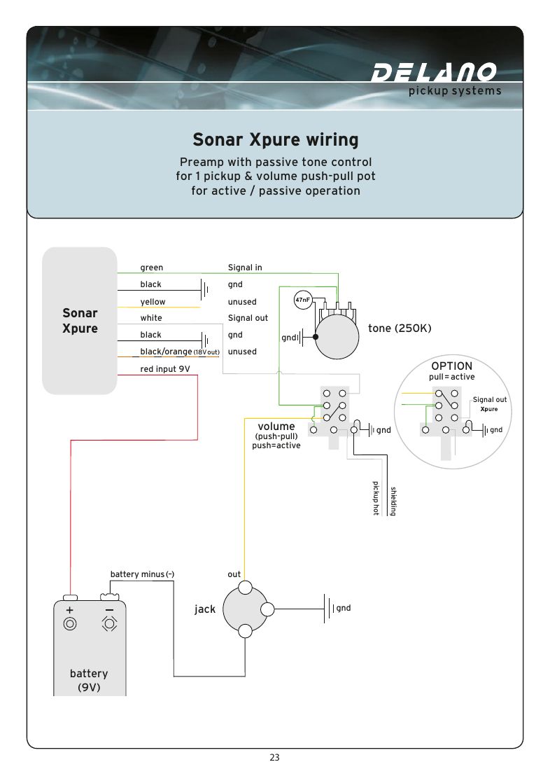
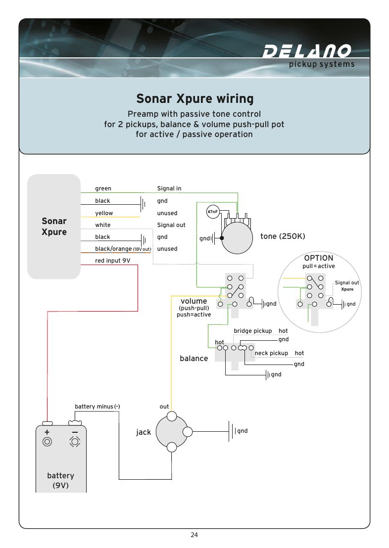
The Xpure's leads, as Delano labels them. Used with an EQ it can feed up to 18 V; with passive tone only, the yellow lead and the 18 V output are left unused.
| Sheets | Page 21: 18 V power distribution. Page 22: passive tone, 2 pickups and 2 volume pots. Page 23: 1 pickup, push-pull volume. Page 24: 2 pickups, balance and push-pull volume. Page 25: 2 pickups, volume and push-pull volume |
|---|---|
| Push-pull (option) | Drawn as pull = active or push = active; choose when wiring |
| Tone pot | 250K |
| # | From | To | Notes |
|---|---|---|---|
| 1 | Green | Pickup signal in | |
| 2 | Black | Ground | |
| 3 | Yellow | Signal input to an EQ | Unused in the passive-tone layouts |
| 4 | White | Signal out | |
| 5 | Red | 9 V input (battery +) | |
| 6 | Black/orange | 18 V out to an EQ | Unused in the passive-tone layouts |
FAQ
What do the Delano 4-conductor wire colours mean?
White, green, brown and yellow are the coil leads. In series: green hot, brown ground, white and yellow joined. In parallel: white and green hot, brown and yellow ground. Single coil: green hot, the rest to ground.
Which push-pull position is series on a Delano pickup?
It depends on the sheet: on the series/parallel diagrams push is parallel and pull is series; on the series/single diagram push is series and pull is single coil.
What are the leads on a Delano Sonar preamp?
Green signal in, yellow out, red +9 V and black ground, plus grey, green and blue leads to each EQ pot.