EMG B157 Pickup Buss Wiring Diagram
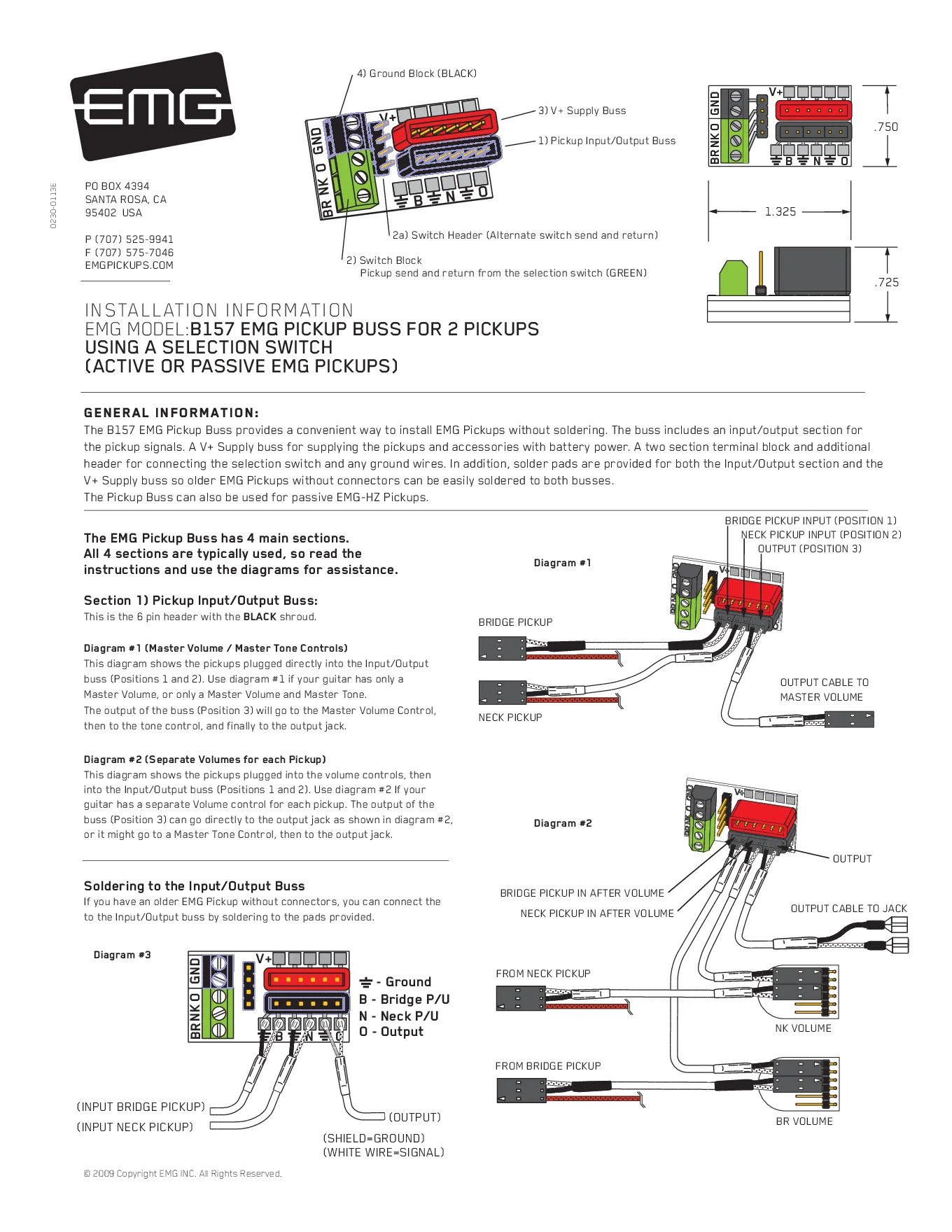
The EMG B157 Pickup Buss lets you install two EMG pickups with a selector switch without soldering. It works with active EMGs and passive EMG-HZ pickups. The sheet explains its four sections, with diagrams for master-volume and separate-volume setups.
Key specs
- Size: 1.325" x 0.750", 0.725" tall.
- 1) Input/output buss (black 6-pin header): position 1 = bridge pickup in, 2 = neck pickup in, 3 = output.
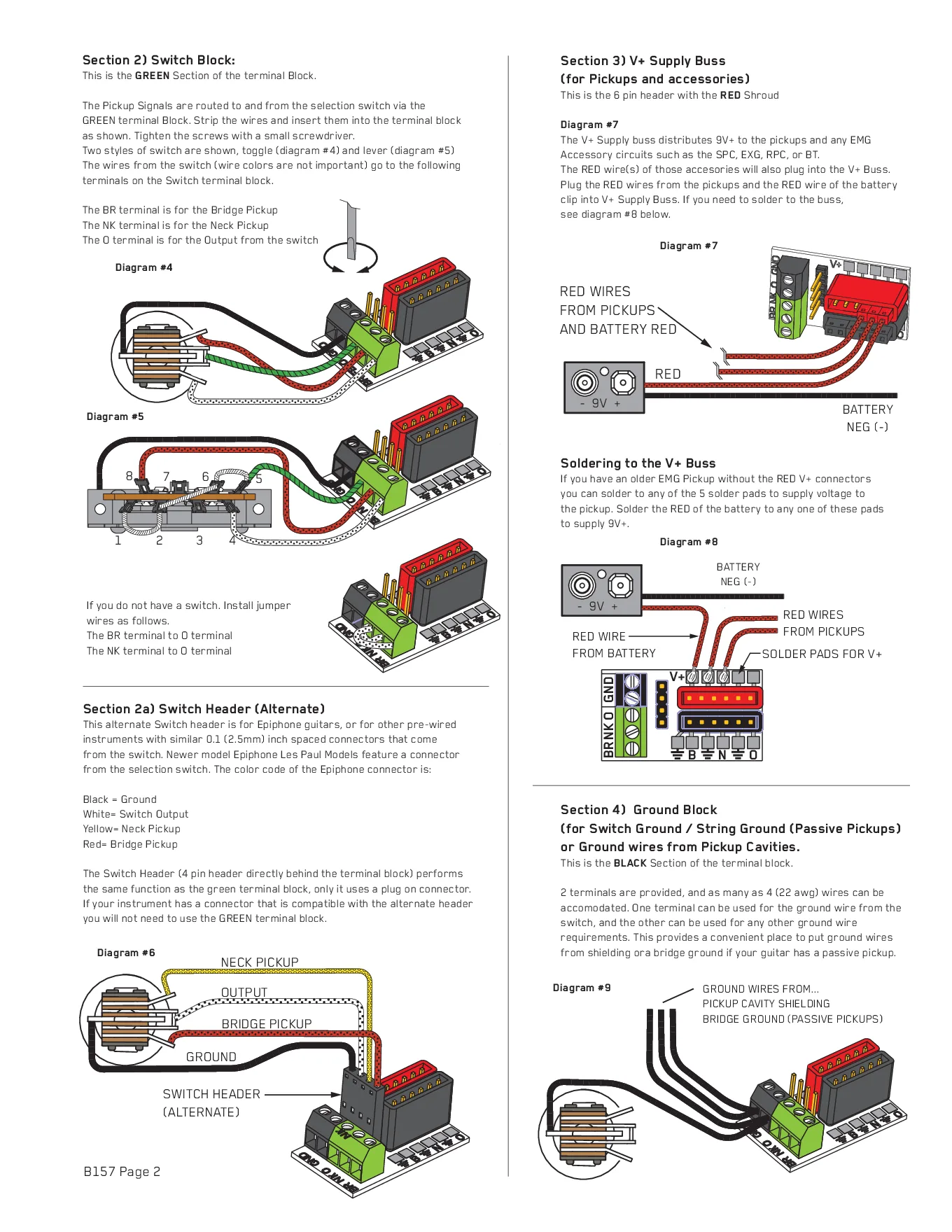
- 2) Switch block (green terminals): BR = bridge, NK = neck, O = switch output. Wire colors from the switch don't matter. With no switch, jumper BR to O and NK to O.
- 2a) Alternate 4-pin switch header for Epiphone-style connectors: black = ground, white = switch output, yellow = neck, red = bridge.
- 3) V+ supply buss (red 6-pin header): the pickup reds and the battery red plug in here. Solder pads are there for older EMGs.
- 4) Ground block (black terminals): switch ground, cavity shielding, and bridge ground for passive pickups. Up to 4 wires (22 AWG).
- Diagram #1 is master volume (and tone) only. Diagram #2 is a separate volume for each pickup.
Every diagram, wire by wire
EMG's B157 pickup buss as text: the two hookups and what each section of the buss is for.
- EMG B157 Diagram 1: master volume and tone
- EMG B157 Diagram 2: separate volume for each pickup
- EMG B157: selector switch, power and ground blocks
How to read these
- Most B157 connections plug on or screw in, no soldering.
- One 9V battery feeds everything through the V+ buss.
EMG B157 Diagram 1: master volume and tone
Both pickups plug straight into the buss. Position 3 (output) goes to the master volume, then the tone, then the jack.
You need: EMG B157 pickup buss, 2 EMG pickups, master volume (and master tone).
| # | From | To | Notes |
|---|---|---|---|
| 1 | Bridge pickup: Cable plug | B157 (black): Position 1 | |
| 2 | Neck pickup: Cable plug | B157 (black): Position 2 | |
| 3 | B157 (black): Position 3 | Master volume: Input | |
| 4 | Master volume: Output | Master tone: Input | |
| 5 | Master tone: Output | Output jack: Tip |
Step by step
- Pickups. Bridge pickup to position 1, neck pickup to position 2.
- Output. Position 3 to the master volume, then to the master tone, then to the jack.
- Test. Plug in at low volume and tap each pickup's pole pieces with a screwdriver. Turn each knob end to end before closing the cavity.
EMG B157 Diagram 2: separate volume for each pickup
Each pickup goes through its own volume first, then into the buss. Position 3 goes to the jack (or a master tone first).
You need: EMG B157, 2 volume controls.
| # | From | To | Notes |
|---|---|---|---|
| 1 | Bridge pickup: Cable plug | Bridge volume: Input | |
| 2 | Neck pickup: Cable plug | Neck volume: Input | |
| 3 | Bridge volume: Output | B157 (black): Position 1 | |
| 4 | Neck volume: Output | B157 (black): Position 2 | |
| 5 | B157 (black): Position 3 | Output jack: Tip | Or to a master tone first |
Step by step
- Pickups to volumes. Plug each pickup into its own volume control.
- Volumes to the buss. Bridge volume to position 1, neck volume to position 2.
- Output. Position 3 to the output jack, or to a master tone and then the jack.
- Test. Plug in at low volume and tap each pickup's pole pieces with a screwdriver. Turn each knob end to end before closing the cavity.
EMG B157: selector switch, power and ground blocks
The green terminal block connects the selector switch, the red header carries battery power, and the black terminal block takes extra ground wires.
You need: EMG B157, selector switch (toggle or lever), 9V battery clip.
| Section | What goes there |
|---|---|
| 1. Input/output buss (black shroud) | Bridge pickup position 1, neck pickup position 2, output position 3. Solder pads for older pickups without connectors. |
| 2. Switch block (green terminals) | BR = bridge pickup to the switch, NK = neck pickup to the switch, O = switch output. Wire colors don't matter. |
| 2a. Switch header (alternate) | Plug-on header for Epiphone-style switch connectors: black = ground, white = switch output, yellow = neck, red = bridge. |
| 3. V+ supply buss (red shroud) | Red wires from the pickups, any EMG accessories (SPC, EXG, RPC, BT) and the battery clip red. |
| 4. Ground block (black terminals) | Switch ground, cavity shielding, and a bridge ground only if you use passive pickups. Up to 4 wires (22 AWG). |
| Jumper | From | To |
|---|---|---|
| 1 | BR terminal | O terminal |
| 2 | NK terminal | O terminal |
Step by step
- Switch. Strip the switch wires and screw them into the green block: bridge to BR, neck to NK, output to O. No switch: jumper BR to O and NK to O.
- Power. Plug the pickups' red wires and the battery red onto the V+ buss. Battery black goes to the jack ring.
- Ground. Put the switch ground and any shielding wires in the black ground block.
- Test. Plug in at low volume and tap each pickup's pole pieces with a screwdriver. Turn each knob end to end before closing the cavity.
- The B157 also works with passive EMG-HZ pickups. Their red wire is a coil wire, not power: don't put it on the V+ buss.
Parts in this diagram
FAQ
Does the B157 need soldering?
No, for EMG pickups with connectors. Solder pads are there for older EMGs without them.
Can I use the B157 without a selector switch?
Yes. Jumper BR to O and NK to O on the switch block.
Does it work with passive EMG-HZ pickups?
Yes. EMG says the Pickup Buss can be used for EMG-HZ pickups.
Related diagrams
- EMG J, JA & JCS Installation and Wiring
- EMG-HZ Bass Pickup Wiring Diagram (35HZ, 40HZ, 45HZ)
- All bass wiring diagrams
- Manuals and dimension drawings
Questions about your install? Email sales@bestbassgear.com.