EMG-HZ Bass Pickup Wiring Diagram (35HZ, 40HZ, 45HZ)
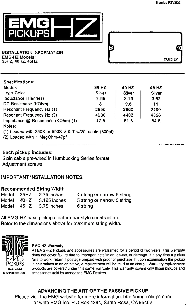
EMG-HZ pickups are EMG's passive soapbar bass pickups. They come with a 5-pin cable prewired for series humbucking. This sheet covers the 35HZ, 40HZ and 45HZ: specs, the coil color code, and wiring for one or two pickups with volume, tone and a selector switch.
Key specs
- DC resistance: 8K (35HZ), 9.6K (40HZ), 11K (45HZ). Inductance 2.65 / 3.15 / 3.62 H.
- Recommended string width: 35HZ 2.75" (4 string or narrow 5), 40HZ 3.125" (5 or narrow 6), 45HZ 3.75" (6 string).
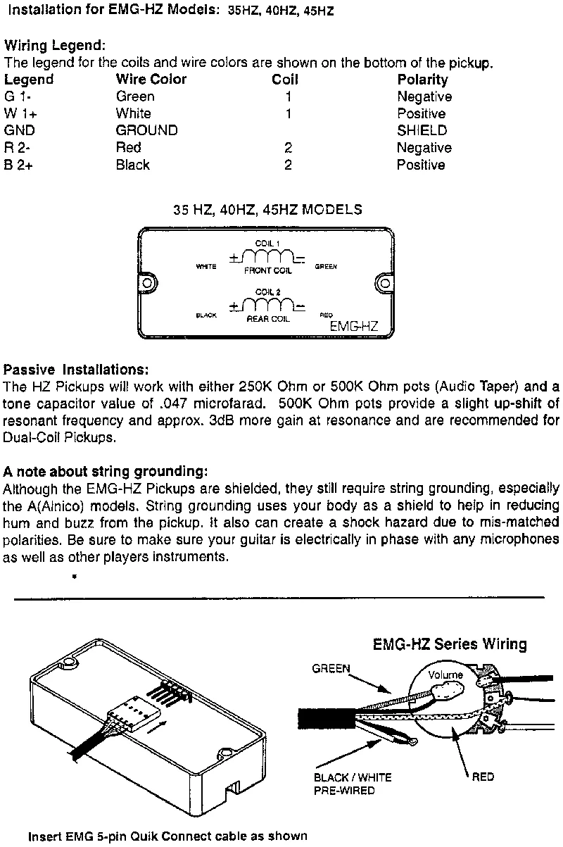
- Wire colors: green = coil 1 negative, white = coil 1 positive, red = coil 2 negative, black = coil 2 positive. The bare wire is the shield/ground.
- These are passive. The red wire is a coil wire, NOT battery power.
- Pots: 250K or 500K audio taper. Tone cap: .047 uF. EMG recommends 500K for dual-coil pickups: slightly higher resonance and about 3 dB more gain.
- Unlike EMG actives, HZ pickups need string grounding, especially the alnico models.
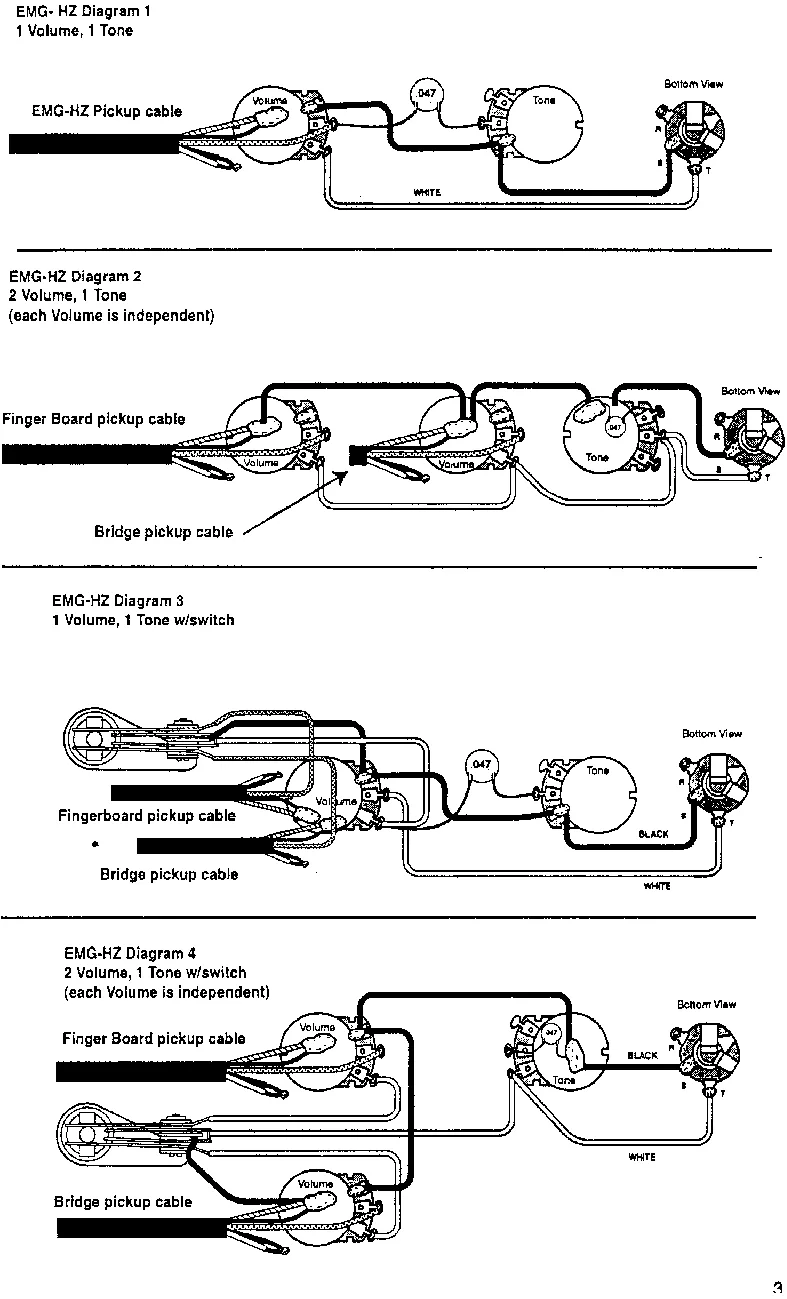
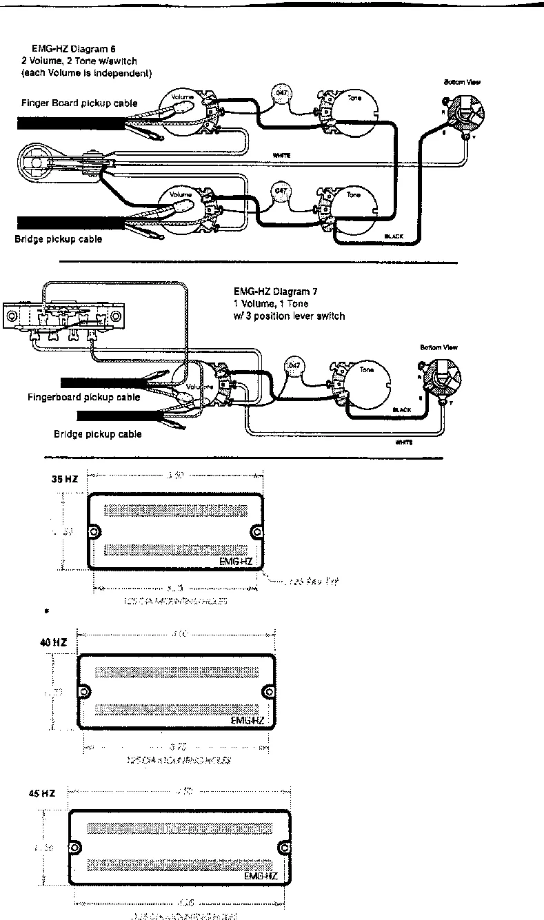
- Diagrams: 1 vol / 1 tone; 2 independent vols / 1 tone; 1 vol / 1 tone with toggle; 2 vols / 1 tone with toggle; 2 vols / 2 tones with toggle; 1 vol / 1 tone with 3-way lever switch.
Every diagram, wire by wire
Here are all six EMG-HZ layouts from EMG's sheet as text: a connection diagram, a wire-by-wire table and the steps for each. The original scanned pages and the PDF are above. EMG's sheet skips Diagram 5.
- EMG-HZ Diagram 1: 1 volume, 1 tone (one pickup)
- EMG-HZ Diagram 2: 2 volumes, 1 tone (independent volumes)
- EMG-HZ Diagram 3: 1 volume, 1 tone with a 3-way toggle
- EMG-HZ Diagram 4: 2 volumes, 1 tone with a 3-way toggle
- EMG-HZ Diagram 6: 2 volumes, 2 tones with a 3-way toggle
- EMG-HZ Diagram 7: 1 volume, 1 tone with a 3-position lever switch
How to read these
- The EMG-HZ cable at the control end is a hot center wire plus a braided shield. The braid is ground.
- Pot lugs: lug 2 is the middle lug. Lug 1 is the outer lug that goes to ground, lug 3 is the other outer lug. If a knob works backwards, swap the wires on lugs 1 and 3.
- Ground means the back of a pot casing. Join all pot casings with a bare wire so they share one ground.
- Use 250K or 500K audio-taper pots. EMG recommends 500K with these pickups.
EMG-HZ Diagram 1: 1 volume, 1 tone (one pickup)
One EMG-HZ pickup into a volume pot, a tone pot with a 0.047 µF cap, and a mono output jack.
You need: 1 EMG-HZ pickup, 2 pots (250K or 500K audio-taper): volume and tone, 0.047 µF capacitor, mono output jack.
| # | From | To | Notes |
|---|---|---|---|
| 1 | Pickup: Hot (center wire) | Volume: Lug 3 (in) | Pickup signal into the volume |
| 2 | Pickup: Braid / shield | Ground (back of a pot casing) | Solder the braid to the volume casing |
| 3 | Volume: Lug 2 (out) | Output jack: Tip | EMG drawing: white wire |
| 4 | Volume: Lug 2 (out) | 0.047 µF cap: Lead A | Tone circuit takes signal from the volume output |
| 5 | 0.047 µF cap: Lead B | Tone: Lug 2 | |
| 6 | Tone: Lug 1 | Ground (back of a pot casing) | Bend the lug to the casing or use a short wire |
| 7 | Volume: Lug 1 | Ground (back of a pot casing) | |
| 8 | Output jack: Sleeve | Ground (back of a pot casing) | EMG drawing: black wire |
| 9 | Bridge ground: Wire from bridge | Ground (back of a pot casing) | Required with EMG-HZ |
Step by step
- Mount the controls. Fit the volume and tone pots and the jack in the cavity before soldering, so wire lengths come out right.
- Ground the pickup. Solder the pickup cable's braid to the back of the volume pot.
- Connect the pickup. Solder the pickup's hot (center) wire to volume lug 3.
- Ground the volume. Connect volume lug 1 to the volume casing.
- Wire the output. Run a wire from volume lug 2 (the middle lug) to the jack tip.
- Wire the tone. Solder one lead of the 0.047 µF cap to volume lug 2 and the other to tone lug 2. Connect tone lug 1 to the tone casing, and join the tone and volume casings with a bare wire.
- Ground the jack. Solder the jack sleeve lug to the back of the nearest pot casing (EMG uses a black wire).
- Ground the strings. Solder the bridge ground wire to a pot casing. EMG-HZ pickups are passive and need it, especially the alnico models.
- Test. Plug in at low volume and tap each pickup's pole pieces with a screwdriver. Turn each knob end to end. If a knob works backwards, swap the wires on its lugs 1 and 3.
EMG-HZ Diagram 2: 2 volumes, 1 tone (independent volumes)
Two EMG-HZ pickups, each on its own volume, sharing one tone and the output jack. The volumes are wired independent: turning one all the way down does not cut the other pickup.
You need: 2 EMG-HZ pickups, 3 pots (250K or 500K audio-taper): neck volume, bridge volume, tone, 0.047 µF capacitor, mono output jack.
| # | From | To | Notes |
|---|---|---|---|
| 1 | Neck pickup: Hot (center wire) | Neck volume: Lug 2 (in) | Into the middle lug: that is what makes it independent |
| 2 | Neck pickup: Braid / shield | Ground (back of a pot casing) | |
| 3 | Bridge pickup: Hot (center wire) | Bridge volume: Lug 2 (in) | Into the middle lug |
| 4 | Bridge pickup: Braid / shield | Ground (back of a pot casing) | |
| 5 | Neck volume: Lug 3 (out) | Output jack: Tip | Output, EMG drawing: white wire |
| 6 | Bridge volume: Lug 3 (out) | Neck volume: Lug 3 (out) | Joins both volume outputs |
| 7 | Bridge volume: Lug 3 (out) | 0.047 µF cap: Lead A | |
| 8 | 0.047 µF cap: Lead B | Tone: Lug 2 | |
| 9 | Tone: Lug 1 | Ground (back of a pot casing) | |
| 10 | Neck volume: Lug 1 | Ground (back of a pot casing) | |
| 11 | Bridge volume: Lug 1 | Ground (back of a pot casing) | |
| 12 | Output jack: Sleeve | Ground (back of a pot casing) | |
| 13 | Bridge ground: Wire from bridge | Ground (back of a pot casing) | Required with EMG-HZ |
Step by step
- Mount the controls. Fit both volumes, the tone pot and the jack, and join all three pot casings with a bare wire.
- Ground the pickups. Solder each pickup cable's braid to the back of its volume pot.
- Connect the pickups. Solder the neck pickup's hot wire to neck volume lug 2, and the bridge pickup's hot wire to bridge volume lug 2. The pickup goes on the middle lug, not an outer lug: this keeps the volumes independent.
- Ground the volumes. Connect lug 1 of each volume to its casing.
- Join the outputs. Run a wire from bridge volume lug 3 to neck volume lug 3, then from neck volume lug 3 to the jack tip.
- Wire the tone. Solder the 0.047 µF cap from a volume lug 3 to tone lug 2, and connect tone lug 1 to its casing.
- Ground the jack. Solder the jack sleeve lug to the back of the nearest pot casing (EMG uses a black wire).
- Ground the strings. Solder the bridge ground wire to a pot casing. EMG-HZ pickups are passive and need it, especially the alnico models.
- Test. Plug in at low volume and tap each pickup's pole pieces with a screwdriver. Turn each knob end to end. If a knob works backwards, swap the wires on its lugs 1 and 3.
- Standard J-bass wiring puts the pickup on lug 3 and takes the output from lug 2. That works too, but then turning either volume to zero mutes the whole bass. EMG's Diagram 2 uses the independent version.
EMG-HZ Diagram 3: 1 volume, 1 tone with a 3-way toggle
Two EMG-HZ pickups into a 3-way toggle (neck, both, bridge), then one master volume, one tone and the output jack.
You need: 2 EMG-HZ pickups, 3-way toggle switch, 2 pots (250K or 500K audio-taper): volume and tone, 0.047 µF capacitor, mono output jack.
| # | From | To | Notes |
|---|---|---|---|
| 1 | Neck pickup: Hot (center wire) | 3-way toggle: Neck lug | |
| 2 | Bridge pickup: Hot (center wire) | 3-way toggle: Bridge lug | |
| 3 | Neck pickup: Braid / shield | Ground (back of a pot casing) | |
| 4 | Bridge pickup: Braid / shield | Ground (back of a pot casing) | |
| 5 | 3-way toggle: Output lugs | Volume: Lug 3 (in) | Toggle output into the volume |
| 6 | Volume: Lug 2 (out) | Output jack: Tip | EMG drawing: white wire |
| 7 | Volume: Lug 2 (out) | 0.047 µF cap: Lead A | |
| 8 | 0.047 µF cap: Lead B | Tone: Lug 2 | |
| 9 | Tone: Lug 1 | Ground (back of a pot casing) | |
| 10 | Volume: Lug 1 | Ground (back of a pot casing) | |
| 11 | Output jack: Sleeve | Ground (back of a pot casing) | EMG drawing: black wire |
| 12 | Bridge ground: Wire from bridge | Ground (back of a pot casing) | Required with EMG-HZ |
Step by step
- Mount the controls. Fit the toggle, volume, tone and jack, and join the pot casings with a bare wire.
- Ground the pickups. Solder both pickup braids to the back of the volume pot.
- Connect the toggle. Solder the neck pickup's hot wire to one outer toggle lug and the bridge pickup's hot wire to the other. Bridge the two inner lugs together: that is the toggle output.
- Toggle to volume. Run a wire from the toggle's inner (output) lugs to volume lug 3. Connect volume lug 1 to its casing.
- Wire the output. Run a wire from volume lug 2 to the jack tip.
- Wire the tone. Solder the 0.047 µF cap from volume lug 2 to tone lug 2, and connect tone lug 1 to its casing.
- Ground the jack. Solder the jack sleeve lug to the back of the nearest pot casing (EMG uses a black wire).
- Ground the strings. Solder the bridge ground wire to a pot casing. EMG-HZ pickups are passive and need it, especially the alnico models.
- Test. Plug in at low volume and tap each pickup's pole pieces with a screwdriver. Turn each knob end to end. If a knob works backwards, swap the wires on its lugs 1 and 3.
- Toggle lug layouts vary by maker. Check yours with a meter: each inner lug should connect to its outer lug in one end position.
EMG-HZ Diagram 4: 2 volumes, 1 tone with a 3-way toggle
Two EMG-HZ pickups, each on its own independent volume, then a 3-way toggle, a master tone and the output jack.
You need: 2 EMG-HZ pickups, 3-way toggle switch, 3 pots (250K or 500K audio-taper): neck volume, bridge volume, tone, 0.047 µF capacitor, mono output jack.
| # | From | To | Notes |
|---|---|---|---|
| 1 | Neck pickup: Hot (center wire) | Neck volume: Lug 2 (in) | |
| 2 | Bridge pickup: Hot (center wire) | Bridge volume: Lug 2 (in) | |
| 3 | Neck pickup: Braid / shield | Ground (back of a pot casing) | |
| 4 | Bridge pickup: Braid / shield | Ground (back of a pot casing) | |
| 5 | Neck volume: Lug 3 (out) | 3-way toggle: Neck lug | |
| 6 | Bridge volume: Lug 3 (out) | 3-way toggle: Bridge lug | |
| 7 | 3-way toggle: Output lugs | Output jack: Tip | EMG drawing: white wire |
| 8 | 3-way toggle: Output lugs | 0.047 µF cap: Lead A | |
| 9 | 0.047 µF cap: Lead B | Tone: Lug 2 | |
| 10 | Tone: Lug 1 | Ground (back of a pot casing) | |
| 11 | Neck volume: Lug 1 | Ground (back of a pot casing) | |
| 12 | Bridge volume: Lug 1 | Ground (back of a pot casing) | |
| 13 | Output jack: Sleeve | Ground (back of a pot casing) | EMG drawing: black wire |
| 14 | Bridge ground: Wire from bridge | Ground (back of a pot casing) | Required with EMG-HZ |
Step by step
- Mount the controls. Fit both volumes, the toggle, the tone pot and the jack, and join all pot casings with a bare wire.
- Ground the pickups. Solder each pickup braid to the back of its volume pot.
- Connect the pickups. Solder each pickup's hot wire to lug 2 (middle) of its own volume. Connect lug 1 of each volume to its casing.
- Volumes to toggle. Run neck volume lug 3 to one outer toggle lug and bridge volume lug 3 to the other. Bridge the two inner toggle lugs.
- Wire the output. Run a wire from the toggle's inner lugs to the jack tip.
- Wire the tone. Solder the 0.047 µF cap from the toggle output to tone lug 2, and connect tone lug 1 to its casing.
- Ground the jack. Solder the jack sleeve lug to the back of the nearest pot casing (EMG uses a black wire).
- Ground the strings. Solder the bridge ground wire to a pot casing. EMG-HZ pickups are passive and need it, especially the alnico models.
- Test. Plug in at low volume and tap each pickup's pole pieces with a screwdriver. Turn each knob end to end. If a knob works backwards, swap the wires on its lugs 1 and 3.
EMG-HZ Diagram 6: 2 volumes, 2 tones with a 3-way toggle
Les Paul-style control set for bass: each EMG-HZ pickup has its own independent volume and tone, and a 3-way toggle picks neck, both or bridge. EMG's sheet has no Diagram 5.
You need: 2 EMG-HZ pickups, 3-way toggle switch, 4 pots (250K or 500K audio-taper): 2 volumes, 2 tones, 2 capacitors, 0.047 µF, mono output jack.
| # | From | To | Notes |
|---|---|---|---|
| 1 | Neck pickup: Hot (center wire) | Neck volume: Lug 2 (in) | |
| 2 | Bridge pickup: Hot (center wire) | Bridge volume: Lug 2 (in) | |
| 3 | Neck pickup: Braid / shield | Ground (back of a pot casing) | |
| 4 | Bridge pickup: Braid / shield | Ground (back of a pot casing) | |
| 5 | Neck volume: Lug 3 (out) | 3-way toggle: Neck lug | |
| 6 | Bridge volume: Lug 3 (out) | 3-way toggle: Bridge lug | |
| 7 | Neck volume: Lug 3 (out) | 0.047 µF cap: Lead A | |
| 8 | 0.047 µF cap: Lead B | Neck tone: Lug 2 | |
| 9 | Neck tone: Lug 1 | Ground (back of a pot casing) | |
| 10 | Bridge volume: Lug 3 (out) | 0.047 µF cap: Lead A | |
| 11 | 0.047 µF cap: Lead B | Bridge tone: Lug 2 | |
| 12 | Bridge tone: Lug 1 | Ground (back of a pot casing) | |
| 13 | 3-way toggle: Output lugs | Output jack: Tip | EMG drawing: white wire |
| 14 | Neck volume: Lug 1 | Ground (back of a pot casing) | |
| 15 | Bridge volume: Lug 1 | Ground (back of a pot casing) | |
| 16 | Output jack: Sleeve | Ground (back of a pot casing) | EMG drawing: black wire |
| 17 | Bridge ground: Wire from bridge | Ground (back of a pot casing) | Required with EMG-HZ |
Step by step
- Mount the controls. Fit the four pots, the toggle and the jack, and join all pot casings with a bare wire.
- Ground the pickups. Solder each pickup braid to the back of its volume pot.
- Connect the pickups. Solder each pickup's hot wire to lug 2 (middle) of its own volume. Connect lug 1 of each volume to its casing.
- Wire each tone. For each pickup, solder a 0.047 µF cap from its volume lug 3 to lug 2 of its tone pot, and connect that tone's lug 1 to its casing.
- Volumes to toggle. Run neck volume lug 3 to one outer toggle lug and bridge volume lug 3 to the other. Bridge the two inner toggle lugs.
- Wire the output. Run a wire from the toggle's inner lugs to the jack tip.
- Ground the jack. Solder the jack sleeve lug to the back of the nearest pot casing (EMG uses a black wire).
- Ground the strings. Solder the bridge ground wire to a pot casing. EMG-HZ pickups are passive and need it, especially the alnico models.
- Test. Plug in at low volume and tap each pickup's pole pieces with a screwdriver. Turn each knob end to end. If a knob works backwards, swap the wires on its lugs 1 and 3.
EMG-HZ Diagram 7: 1 volume, 1 tone with a 3-position lever switch
Two EMG-HZ pickups into a 3-position lever (blade) switch for neck, both or bridge, then a master volume, a tone and the output jack.
You need: 2 EMG-HZ pickups, 3-position lever switch, 2 pots (250K or 500K audio-taper): volume and tone, 0.047 µF capacitor, mono output jack.
| # | From | To | Notes |
|---|---|---|---|
| 1 | Neck pickup: Hot (center wire) | 3-way lever: Neck input | |
| 2 | Bridge pickup: Hot (center wire) | 3-way lever: Bridge input | |
| 3 | Neck pickup: Braid / shield | Ground (back of a pot casing) | |
| 4 | Bridge pickup: Braid / shield | Ground (back of a pot casing) | |
| 5 | 3-way lever: Common (out) | Volume: Lug 3 (in) | |
| 6 | Volume: Lug 2 (out) | Output jack: Tip | EMG drawing: white wire |
| 7 | Volume: Lug 2 (out) | 0.047 µF cap: Lead A | |
| 8 | 0.047 µF cap: Lead B | Tone: Lug 2 | |
| 9 | Tone: Lug 1 | Ground (back of a pot casing) | |
| 10 | Volume: Lug 1 | Ground (back of a pot casing) | |
| 11 | Output jack: Sleeve | Ground (back of a pot casing) | EMG drawing: black wire |
| 12 | Bridge ground: Wire from bridge | Ground (back of a pot casing) | Required with EMG-HZ |
Step by step
- Mount the controls. Fit the lever switch, volume, tone and jack, and join the pot casings with a bare wire.
- Ground the pickups. Solder both pickup braids to the back of the volume pot.
- Connect the switch. Solder the neck pickup's hot wire to the switch's neck-position lug and the bridge pickup's hot wire to its bridge-position lug, on one pole of the switch.
- Switch to volume. Run a wire from that pole's common lug to volume lug 3. Connect volume lug 1 to its casing.
- Wire the output. Run a wire from volume lug 2 to the jack tip.
- Wire the tone. Solder the 0.047 µF cap from volume lug 2 to tone lug 2, and connect tone lug 1 to its casing.
- Ground the jack. Solder the jack sleeve lug to the back of the nearest pot casing (EMG uses a black wire).
- Ground the strings. Solder the bridge ground wire to a pot casing. EMG-HZ pickups are passive and need it, especially the alnico models.
- Test. Plug in at low volume and tap each pickup's pole pieces with a screwdriver. Turn each knob end to end. If a knob works backwards, swap the wires on its lugs 1 and 3.
- Lever switch lug order differs by brand. Check with a meter which lug connects to common in each position before soldering.
Parts in this diagram
FAQ
Do EMG-HZ pickups need a battery?
No. They're passive. The red wire is a coil wire, not a power wire.
250K or 500K pots for EMG-HZ?
Either works. EMG recommends 500K for dual-coil pickups: a slight bump in resonant frequency and about 3 dB more gain.
Do I need to ground the bridge with EMG-HZ?
Yes. Unlike EMG active pickups, HZ pickups need string grounding.
Which HZ fits my bass?
Go by string width: 35HZ up to 2.75", 40HZ up to 3.125", 45HZ up to 3.75".
Related diagrams
- EMG J, JA & JCS Installation and Wiring
- EMG B157 Pickup Buss Wiring Diagram
- All bass wiring diagrams
- Manuals and dimension drawings
Questions about your install? Email sales@bestbassgear.com.