EMG J, JA & JCS Installation and Wiring
EMG's instructions for the J, JA and JCS active Jazz bass sets (4 and 5 string). The sheet has specs, the long (bridge) and short (neck) housing dimensions, the solderless J-bass hookup (two volumes and a master tone), a balance-control option, and soldering notes for panel jacks and older EMGs.
Key specs
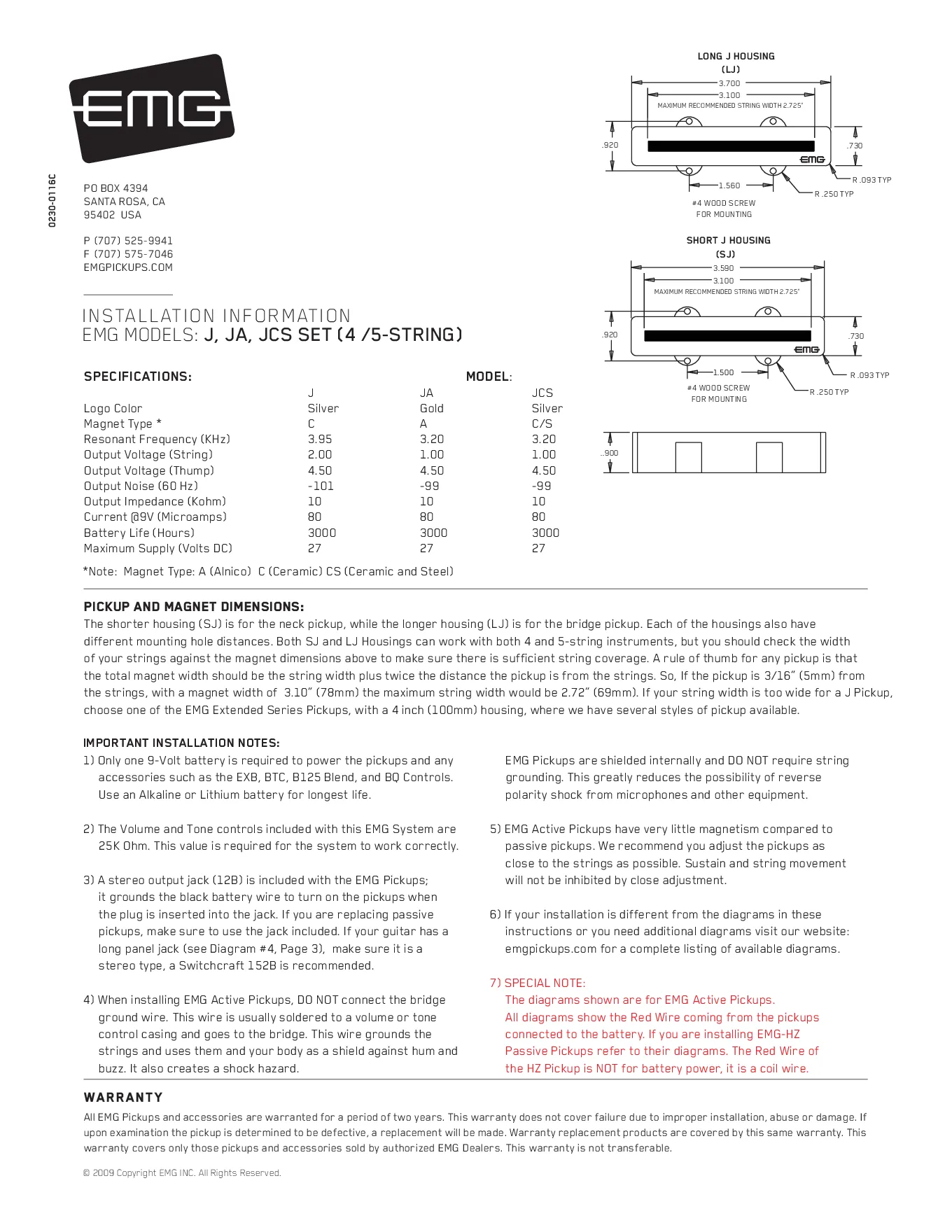
- Housings: LJ (bridge) 3.700" long and SJ (neck) 3.590" long, both 0.920" wide. Magnet length 3.100" on both. Maximum recommended string width 2.725".
- Magnets: J ceramic, JA alnico, JCS ceramic and steel. Resonant frequency 3.95 kHz (J) and 3.20 kHz (JA, JCS).
- Output (string): 2.00 (J), 1.00 (JA, JCS). Impedance is 10K. Current draw is 80 microamps at 9V, about 3000 hours of battery life. Max supply is 27V DC.
- Use the 25K volume and tone pots that come with the set. EMG says this value is required.
- One 9V battery runs the pickups and any EMG accessories (EXB, BTC, B125, BQ).
- The included 12B stereo jack switches the battery on when you plug in. For a long panel jack, use a stereo type. EMG recommends a Switchcraft 152B.
- Do NOT connect the bridge ground wire. EMG actives are shielded and don't need string grounding.
- Rule of thumb: magnet width = string width + 2x the pickup-to-string distance. If your strings are wider than that, EMG points you to their 4" Extended Series.
Every diagram, wire by wire
EMG's J, JA and JCS layouts as text: solderless volume/volume/tone, the balance-control setup, the long panel jack, and two pickups with a selector switch.
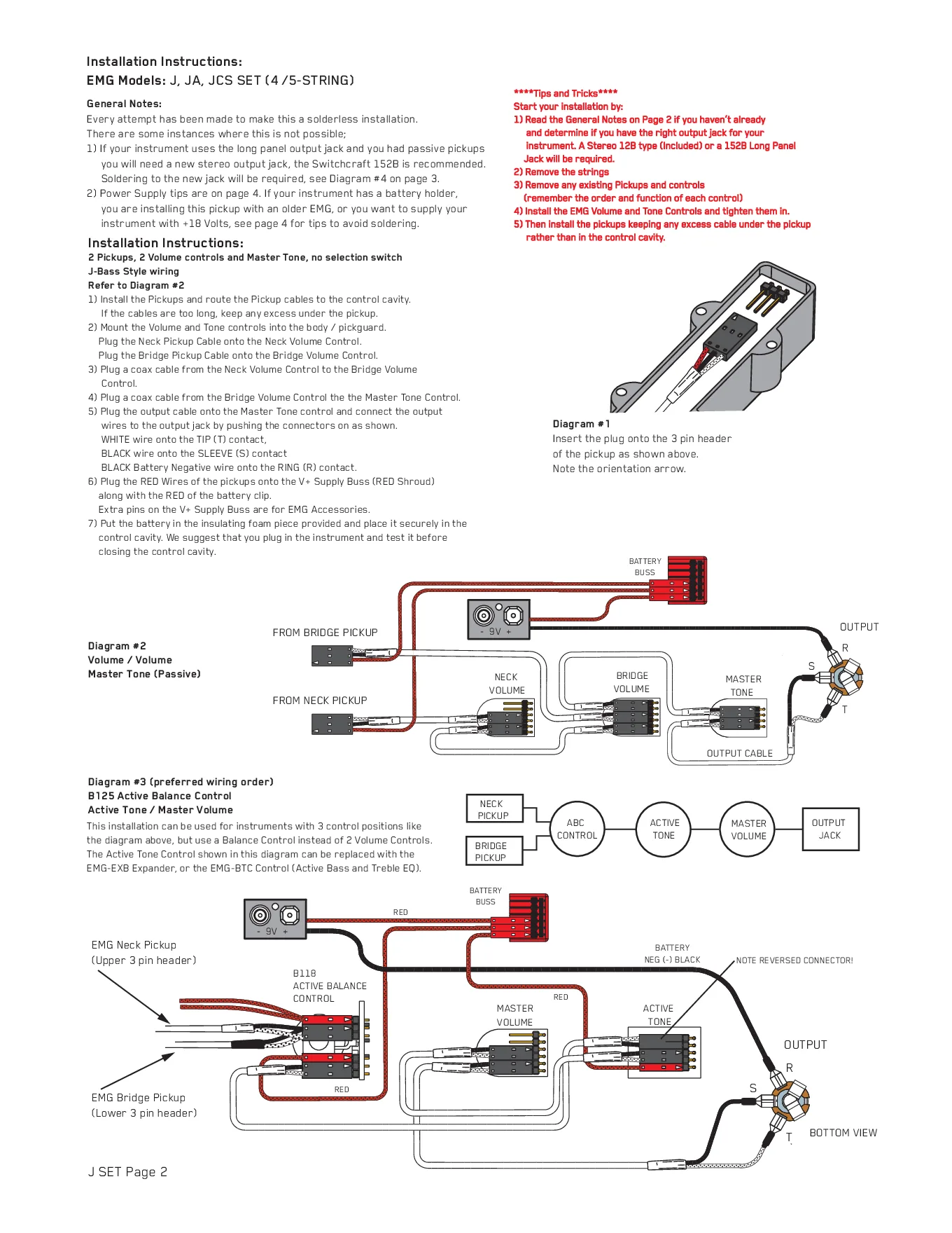
- EMG J set Diagram 2: volume, volume, master tone (solderless)
- EMG J set Diagram 3: balance control, active tone, master volume
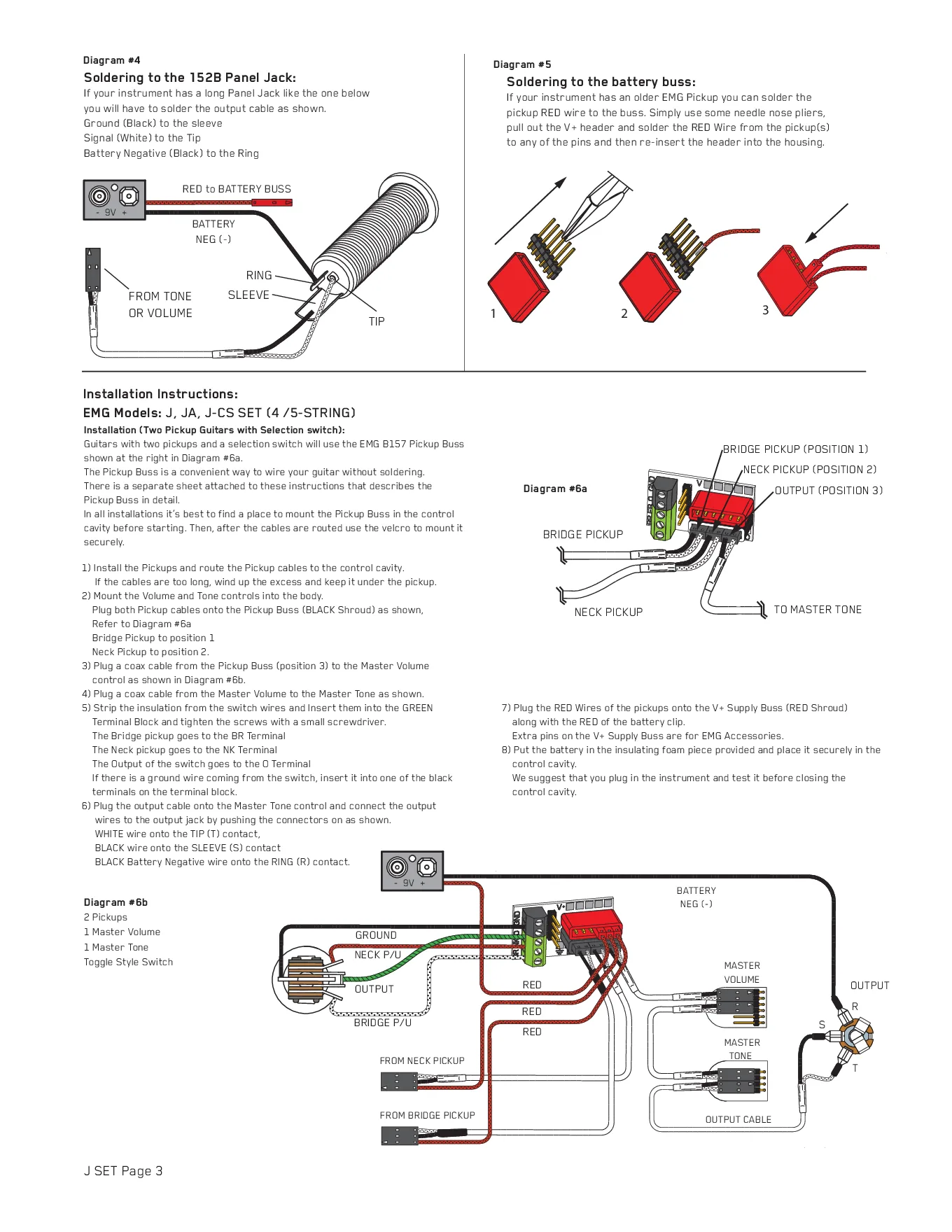
- EMG J set Diagram 4: soldering to a long panel jack (Switchcraft 152B)
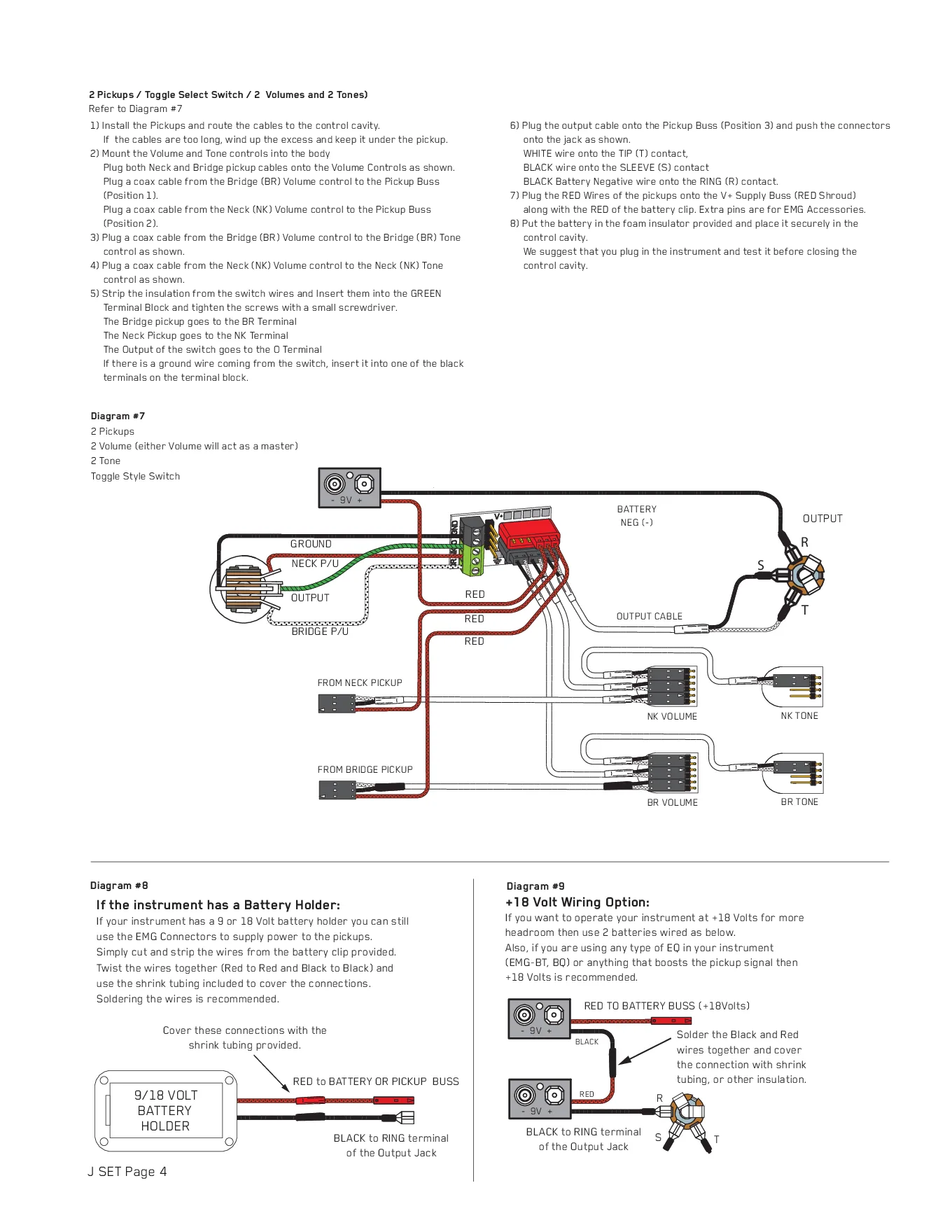
- EMG J set Diagram 6: two pickups with a selector switch (B157 pickup buss)
How to read these
- These are EMG active pickups with plug-in connectors: most connections plug on, no soldering.
- One 9V battery powers the pickups and any EMG accessories.
- Use the stereo jack: its ring connects the battery only when a plug is in.
EMG J set Diagram 2: volume, volume, master tone (solderless)
Standard J-bass layout with EMG's plug-in controls: each pickup plugs into its own 25K volume, then the master tone, then the stereo jack.
You need: EMG J, JA or JCS set, 2 EMG 25K volume controls, EMG 25K tone control, 2 coax jumper cables and output cable, EMG battery buss, 9V battery clip, stereo jack (12B, included).
| # | From | To | Notes |
|---|---|---|---|
| 1 | Neck pickup: Cable plug | Neck volume: Pickup header | |
| 2 | Bridge pickup: Cable plug | Bridge volume: Pickup header | |
| 3 | Neck volume: Output header | Bridge volume: Coax in | Coax cable |
| 4 | Bridge volume: Output header | Master tone: Coax in | Coax cable |
| 5 | Master tone: Output cable | Stereo jack: Tip | White wire |
| 6 | Master tone: Output cable | Stereo jack: Sleeve | Black wire |
| 7 | 9V battery: Black (−) | Stereo jack: Ring | Black battery wire |
| 8 | Neck pickup: Red (power) | Battery buss: V+ (red shroud) | |
| 9 | Bridge pickup: Red (power) | Battery buss: V+ (red shroud) | |
| 10 | Battery buss: V+ (red shroud) | 9V battery: Red (+) | Battery red on the same buss |
Step by step
- Route the cables. Install the pickups and run their cables to the cavity. Keep extra cable under the pickups, not in the cavity.
- Fit the controls. Mount the two volumes and the tone. Plug the neck pickup into the neck volume and the bridge pickup into the bridge volume.
- Chain the controls. Coax cable from the neck volume to the bridge volume, then from the bridge volume to the master tone.
- Output. Plug the output cable onto the master tone. Push its WHITE wire onto the jack tip and BLACK onto the sleeve; push the battery's BLACK onto the ring.
- Power. Plug both pickups' RED wires and the battery clip's RED onto the V+ supply buss (red shroud).
- Test. Put the battery in its foam sleeve, plug in and test before closing the cavity.
- Use the 25K controls that come with the set: the system needs that value.
- Do not connect a bridge ground wire with EMG active pickups. They are shielded, and it adds a shock risk.
EMG J set Diagram 3: balance control, active tone, master volume
For 3-knob basses: an EMG B125 or B118 active balance control takes both pickups, then an active tone, then the master volume and the jack.
You need: EMG J set, EMG B125 or B118 active balance control, EMG active tone (or EXB, or BTC), EMG master volume, battery buss and 9V clip, stereo jack.
| # | From | To | Notes |
|---|---|---|---|
| 1 | Neck pickup: Cable plug | Balance control: Upper 3-pin header | |
| 2 | Bridge pickup: Cable plug | Balance control: Lower 3-pin header | |
| 3 | Balance control: Output | Active tone: Input | |
| 4 | Active tone: Output | Master volume: Input | |
| 5 | Master volume: Output cable | Stereo jack: Tip | White |
| 6 | Master volume: Output cable | Stereo jack: Sleeve | Black |
Step by step
- Pickups to the balance. Neck pickup into the upper 3-pin header of the balance control, bridge pickup into the lower one.
- Chain the controls. Balance control to the active tone, active tone to the master volume. EMG marks one connector as reversed: match its drawing.
- Output and power. Master volume output cable to the jack: white to tip, black to sleeve, battery black to ring. All red wires (pickups, controls, battery) go to the V+ buss.
- Test. Plug in at low volume and tap each pickup's pole pieces with a screwdriver. Turn each knob end to end before closing the cavity.
- The active tone can be swapped for an EMG EXB or BTC control.
EMG J set Diagram 4: soldering to a long panel jack (Switchcraft 152B)
If the bass has a long panel jack, it must be a stereo type. Solder the output cable to it.
You need: Switchcraft 152B stereo panel jack.
| # | From | To | Notes |
|---|---|---|---|
| 1 | Output cable: White (signal) | 152B jack: Tip | |
| 2 | Output cable: Black (ground) | 152B jack: Sleeve | |
| 3 | 9V battery: Black (−) | 152B jack: Ring |
Step by step
- Solder the jack. White to tip, black to sleeve, battery black to ring.
- Test. Plug in at low volume and tap each pickup's pole pieces with a screwdriver. Turn each knob end to end before closing the cavity.
EMG J set Diagram 6: two pickups with a selector switch (B157 pickup buss)
With a pickup selector, both pickups plug into the EMG B157 pickup buss. The buss runs them through the switch and on to the master volume and tone.
You need: EMG J set, EMG B157 pickup buss, master volume and master tone, selector switch.
| # | From | To | Notes |
|---|---|---|---|
| 1 | Bridge pickup: Cable plug | B157 buss: Position 1 | |
| 2 | Neck pickup: Cable plug | B157 buss: Position 2 | |
| 3 | B157 buss: Position 3 (out) | Master volume: Input | Coax cable |
| 4 | Master volume: Output | Master tone: Input | Coax cable |
| 5 | Master tone: Output cable | Stereo jack: Tip | White |
| 6 | Master tone: Output cable | Stereo jack: Sleeve | Black |
Step by step
- Mount the buss. Find a spot for the B157 in the cavity, route the pickup cables, then fix the buss with its Velcro.
- Pickups. Bridge pickup to position 1, neck pickup to position 2 on the black-shroud header.
- Controls. Coax from position 3 to the master volume, then from the master volume to the master tone. Tone output cable to the jack as before.
- Switch. Strip the switch wires and screw them into the green terminal block: bridge to BR, neck to NK, switch output to O.
- Power. Pickup reds and the battery red onto the V+ buss (red shroud).
- Test. Plug in at low volume and tap each pickup's pole pieces with a screwdriver. Turn each knob end to end before closing the cavity.
- The B157 has its own page: see the EMG B157 Pickup Buss diagram.
Parts in this diagram
FAQ
Which housing goes where?
The short SJ housing is the neck pickup. The long LJ housing is the bridge pickup. The mounting holes are spaced differently too.
Can I use my old 250K pots?
No. EMG says the 25K controls that come with the set are required for the system to work correctly.
Do EMG J pickups need a bridge ground?
No. Leave the bridge ground wire disconnected. The pickups are shielded internally.
Will an EMG J fit my 5-string?
Both housings work on 4 and 5 strings. Check your string spread against the 3.10" magnet. The max recommended string width is 2.725".
Related diagrams
- EMG B157 Pickup Buss Wiring Diagram
- EMG-HZ Bass Pickup Wiring Diagram (35HZ, 40HZ, 45HZ)
- All bass wiring diagrams
- Manuals and dimension drawings
Questions about your install? Email sales@bestbassgear.com.