Jazz Bass Series/Parallel Wiring Diagram
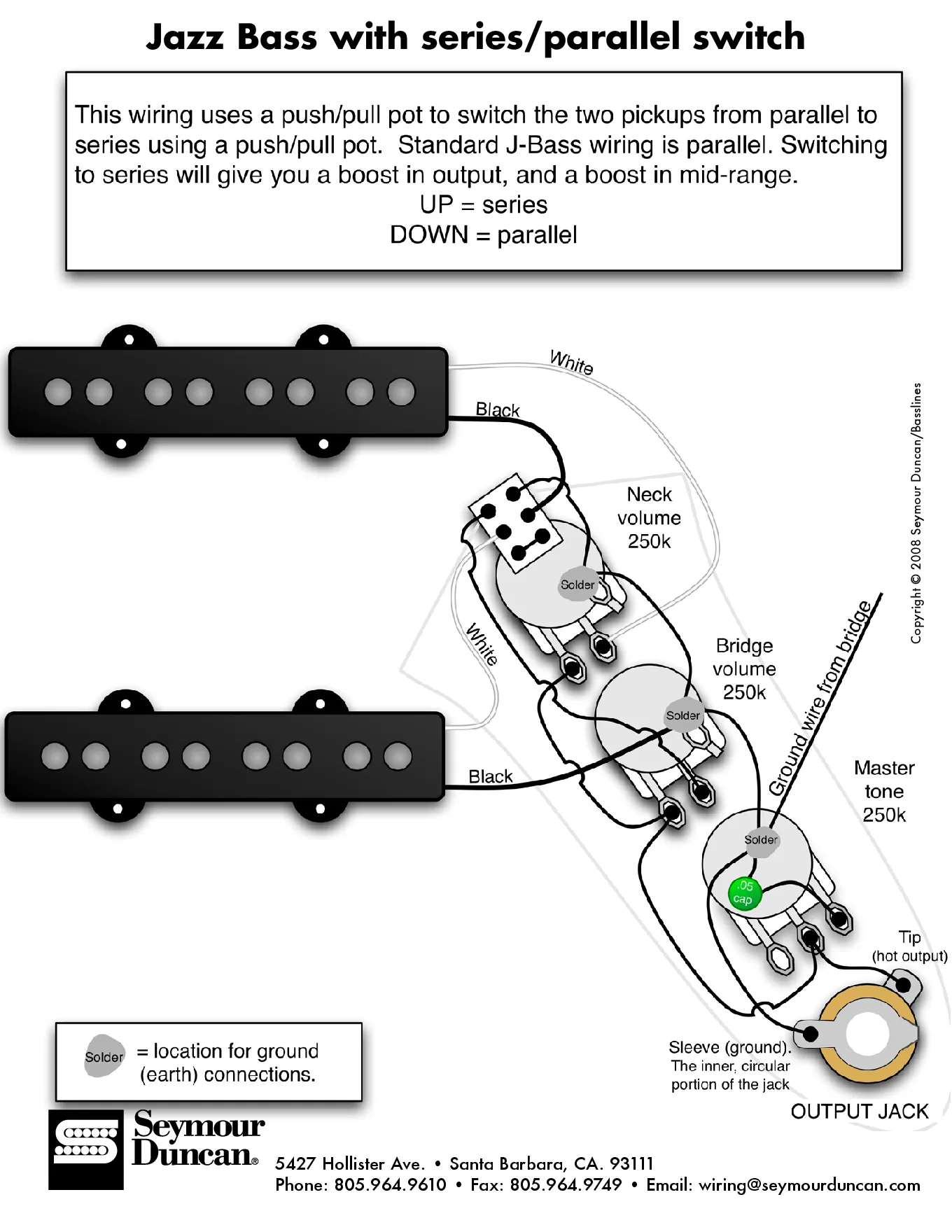
This Seymour Duncan/Basslines diagram adds a series/parallel switch to a standard Jazz Bass using a push/pull pot on the neck volume. Stock J-Bass wiring is parallel. Switching to series boosts output and mid-range.
Before you solder
- Neck volume is a 250K push/pull. Bridge volume is 250K and master tone is 250K.
- Tone cap: .05 uF.
- Pull up = series. Push down = parallel (stock J-Bass sound).
- The ground wire from the bridge goes to the back of the tone pot. Grounds are soldered to the pot backs (marked 'Solder').
- Output jack: tip = hot output, sleeve = ground.
- In this drawing each pickup's white lead is hot and the black lead is ground. Check your own pickup's color code.
Every diagram, wire by wire
The series/parallel mod as text: a connection diagram, a wire-by-wire table and the steps.
How to read these
- Pot lugs: lug 2 is the middle lug. Lug 1 is the outer lug that goes to ground, lug 3 is the other outer lug. If a knob works backwards, swap the wires on lugs 1 and 3.
- Ground means the back of a pot casing (or the jack sleeve). Join all pot casings with a bare wire so they share one ground.
- A push/pull pot has a DPDT switch on the back: two poles, each with a common lug and an up and a down lug.
Jazz Bass series/parallel with a push/pull on the neck volume
Down = parallel (stock J-bass). Up = series: the two pickups are joined end to end for more output and more mids. 250K pots and a .05 µF tone cap.
You need: 250K push/pull pot (neck volume), 250K pot (bridge volume), 250K pot (master tone), 0.05 µF capacitor, mono output jack.
| # | From | To | Notes |
|---|---|---|---|
| 1 | Neck pickup: Hot (white here) | Neck volume: Lug 3 (in) | |
| 2 | Neck pickup: Ground (black here) | Push/pull switch: Pole A common | Neck ground goes through the switch |
| 3 | Bridge pickup: Hot (white here) | Push/pull switch: Pole B common | |
| 4 | Bridge pickup: Ground (black here) | Ground (back of a pot casing) | |
| 5 | Push/pull switch: A down (parallel) | Ground (back of a pot casing) | Parallel: neck ground to ground |
| 6 | Push/pull switch: A up (series) | Push/pull switch: Pole B common | Series: neck ground joins bridge hot |
| 7 | Push/pull switch: B down (parallel) | Bridge volume: Lug 3 (in) | Parallel: bridge hot to its volume |
| 8 | Neck volume: Lug 2 (out) | Master tone: Lug 3 (in) | |
| 9 | Bridge volume: Lug 2 (out) | Master tone: Lug 3 (in) | Volume outputs joined at the tone |
| 10 | Master tone: Lug 3 (to jack) | Output jack: Tip | Same lug 3 |
| 11 | Master tone: Lug 2 | 0.05 µF cap: Lead A | |
| 12 | Neck volume: Lug 1 | Ground (back of a pot casing) | |
| 13 | Bridge volume: Lug 1 | Ground (back of a pot casing) | |
| 14 | Output jack: Sleeve | Ground (back of a pot casing) | |
| 15 | 0.05 µF cap: Lead A | Ground (back of a pot casing) | Other cap lead to the tone casing |
Step by step
- Mount the controls. Fit the 250K push/pull as the neck volume, plus the bridge volume, master tone and jack. Join the pot casings with a bare wire.
- Neck pickup. Neck hot to neck volume lug 3. Neck ground to the common lug of switch pole A.
- Bridge pickup. Bridge hot to the common lug of switch pole B. Bridge ground to a pot casing.
- Switch, parallel side (down). Pole A down-throw to ground. Pole B down-throw to bridge volume lug 3.
- Switch, series side (up). Pole A up-throw to pole B common, so in series the neck's ground lead feeds into the bridge pickup's hot.
- Volumes and tone. Volume lug 1s to ground. Both volume lug 2s to tone lug 3, and tone lug 3 to the jack tip. Tone lug 2 to the 0.05 µF cap, other cap lead to the tone casing.
- Grounds. Jack sleeve and the bridge ground wire to the back of the tone pot.
- Test. Plug in at low volume and tap each pickup's pole pieces with a screwdriver. Turn each knob end to end before closing the cavity.
- In series the bridge volume drops out of the circuit, so the neck volume works as a master.
- Pickup wire colors vary by maker: in this drawing white is hot and black is ground. Check your pickup's color code.
Parts in this diagram
FAQ
What does series do on a Jazz Bass?
It boosts output and mid-range. Standard J-Bass wiring is parallel.
Which knob gets the push/pull?
In this diagram it's the neck volume. Up is series, down is parallel.
What pots and cap does it use?
250K for both volumes and the master tone, with a .05 uF cap on the tone.
Related diagrams
- DiMarzio Model J & Ultra Jazz Wiring Diagram
- 2-Pickup Volume-Blend-Tone Wiring Diagram
- All bass wiring diagrams
- Manuals and dimension drawings
Questions about your install? Email sales@bestbassgear.com.