EMG Bass Wiring Diagrams
EMG bass wiring diagrams, written out as text: all 37 EMG sheets in our library, covering the 35, 40 and 45 series, P, J, TB, Music Man and HB pickups, X series, TW dual-mode pickups and the passive HZ range. Find your pickup for its specs and which hookups apply, then follow the hookup wire by wire. Each has EMG's original drawing and a PDF download.
Before you start
- EMG active pickups are solderless: cables push onto the pickups, pots, buss and jack. You only solder for a long panel jack, an existing battery holder or an older EMG with a bare red wire.
- Output cable colours are the same everywhere: white to the jack tip, black to the sleeve, and the battery clip's black to the ring of the stereo jack.
- Every red wire (pickups, active controls, battery) goes on the red battery buss.
- Don't reconnect the string ground with active EMGs. Passive HZ pickups do get a bridge ground.
- The passive EMG-HZ hookups are on our EMG-HZ wiring page, and the boxed EMG J set (separate pots, B157 buss) is on our EMG J, JA and J-CS page. This page links to them rather than repeating them.
Find your pickup
Standard active pickups (solderless, 25K pots)
- EMG 35 series bass pickups: 35P4, 35P4A, 35P5, 35J, 35JA
- EMG 40 series bass pickups: 40P5, 40J, 40JCS, 40CS, 40DC, 40P, 40PCS
- EMG 45 series bass pickups: 45P, 45PCS, 45J, 45JCS, 45CS, 45DC
- EMG P, PA, P-CS, P5 and P6 bass pickups
- EMG TB series bass pickups: TBP, TBPA, TBP5, TBJ, TBJA, TBCS, TBDC
- EMG MMCS (Music Man 4-string replacement)
- EMG MM5CS (Music Man 5-string replacement)
- EMG HB (bass pickup in a guitar humbucker housing)
- EMG LJ (single long J pickup, 4 or 5-string)
- EMG LJV (vintage-voiced long J pickup, 4-string)
- EMG JV set (vintage-voiced J pair)
- EMG J5, J5A and J5-CS sets (5-string J)
X series (VLPF active tone)
- EMG 35-X series bass pickups: 35P4-X, 35P4A-X, 35P5-X, 35J-X, 35JA-X
- EMG 40-X series bass pickups: 40P5-X, 40J-X, 40JCS-X, 40CS-X, 40DC-X, 40P-X, 40PCS-X
- EMG 45-X series bass pickups: 45P-X, 45PCS-X, 45J-X, 45JCS-X, 45CS-X, 45DC-X
- EMG P-X, PA-X, P-CS-X, P5-X and P6-X bass pickups
- EMG JV-X set (4-string)
J systems with a pre-wired control board
- EMG J, JA and J-CS system (pre-wired control plate)
- EMG J-X, JA-X and J-CS-X system (pre-wired control plate)
TW dual-mode pickups (push-pull coil switch)
- EMG 35-TW (dual-mode, 35 housing)
- EMG 35-TW-X (dual-mode, X series)
- EMG 40-TW (dual-mode, 40 housing)
- EMG 40-TW-X (dual-mode, X series)
- EMG 45-TW (dual-mode, 6-string)
- EMG 45-TW-X (dual-mode, X series, 6-string)
- EMG MMTW (dual-mode Music Man 4-string)
- EMG MM5TW (dual-mode Music Man 5-string)
- EMG TB-TW (dual-mode, TB housing)
Passive HZ pickups (5-wire cable)
- EMG 35-HZ (passive, 35 housing)
- EMG 40-HZ (passive, 40 housing)
- EMG 45-HZ (passive, 6-string)
- EMG TB-HZ (passive, TB housing)
- EMG MMHZ (passive Music Man shape, 4-string)
Passive GZR and J-HZ sets (2-wire cable)
- EMG P-HZ, Geezer Butler GZR model (passive P)
- EMG PJ-HZ set, Geezer Butler GZR model (passive PJ)
- EMG J-HZ / JVHZ set, alnico 2 or alnico 5 (passive J)
The hookups, wire by wire
- EMG active, one pickup: volume only, or volume and tone
- EMG active, two pickups: volume, volume, master tone (J-bass style)
- EMG active, two pickups with a 3-way switch (B245 pickup buss)
- EMG active, two pickups: active balance, active tone, master volume
- EMG X series: volume with the VLPF active tone
- EMG TW pickups: setting the push-pull coil switch
- EMG TW push-pull pot: four ways to use the 25K pot
- EMG TW: one or two TW pickups, complete hookups
- EMG J system: plugging into the pre-wired control board
- EMG: long panel jack, older EMGs, battery holders and 18 V
- EMG-HZ passive pickups: the 5-wire cable and solderless pots
- EMG GZR P-HZ, PJ-HZ and J-HZ/JVHZ sets: 2-wire passive hookups
Standard active pickups (solderless, 25K pots)
EMG 35 series bass pickups: 35P4, 35P4A, 35P5, 35J, 35JA
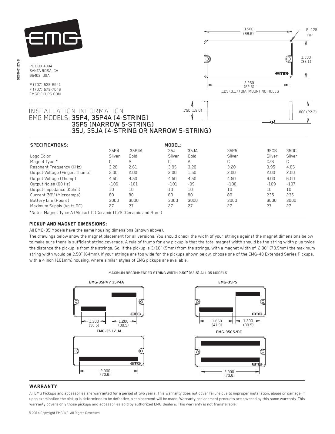
EMG's standard 3.5-inch soapbar-size active pickups for 4-string and narrow 5-string basses. Solderless: 25K volume and tone pots, push-on cables, battery buss and stereo jack are in the box.
String spread: 2.50" (63.5 mm) maximum string spread for all 35 models.
In the box: 25K volume and 25K tone pot, 13.5" pickup cable, two 5.5" connect cables, 6" output cable, stereo output jack, battery buss, 7" battery cable, adjustment screws.
| 35P4 | 35P4A | 35J | 35JA | 35P5 | 35CS | 35DC | |
|---|---|---|---|---|---|---|---|
| Logo | Silver | Gold | Silver | Gold | Silver | Silver | Silver |
| Magnet | C | A | C | A | C | C/S | C |
| Resonant frequency (kHz) | 3.20 | 2.61 | 3.95 | 3.20 | 3.20 | 3.95 | 4.85 |
| Output, finger/thumb (V) | 2.00 | 2.00 | 2.00 | 1.50 | 2.00 | 2.00 | 2.00 |
| Output, thump (V) | 4.50 | 4.50 | 4.50 | 4.50 | 4.50 | 6.00 | 6.00 |
| Noise at 60 Hz (dBV) | -106 | -101 | -101 | -99 | -106 | -109 | -107 |
| Output impedance (kΩ) | 10 | 10 | 10 | 10 | 10 | 10 | 10 |
| Current at 9 V (µA) | 80 | 80 | 80 | 80 | 80 | 235 | 235 |
| Battery life (hours) | 3000 | 3000 | 3000 | 3000 | 3000 | 3000 | 3000 |
Magnet: C = ceramic, A = alnico, C/S = ceramic and steel. Maximum supply 27 V DC.
Hookups on this sheet
- EMG active, one pickup: volume only, or volume and tone
- EMG active, two pickups: volume, volume, master tone (J-bass style)
- EMG active, two pickups with a 3-way switch (B245 pickup buss)
- EMG active, two pickups: active balance, active tone, master volume
- EMG: long panel jack, older EMGs, battery holders and 18 V
- Rule of thumb from EMG: total magnet width should equal the string spread plus twice the pickup-to-string distance. Wider basses need the 40 series (4-inch housing).
- The 35CS and 35DC are in the spec table but not in the sheet's model list; they share the same housing.
EMG 40 series bass pickups: 40P5, 40J, 40JCS, 40CS, 40DC, 40P, 40PCS
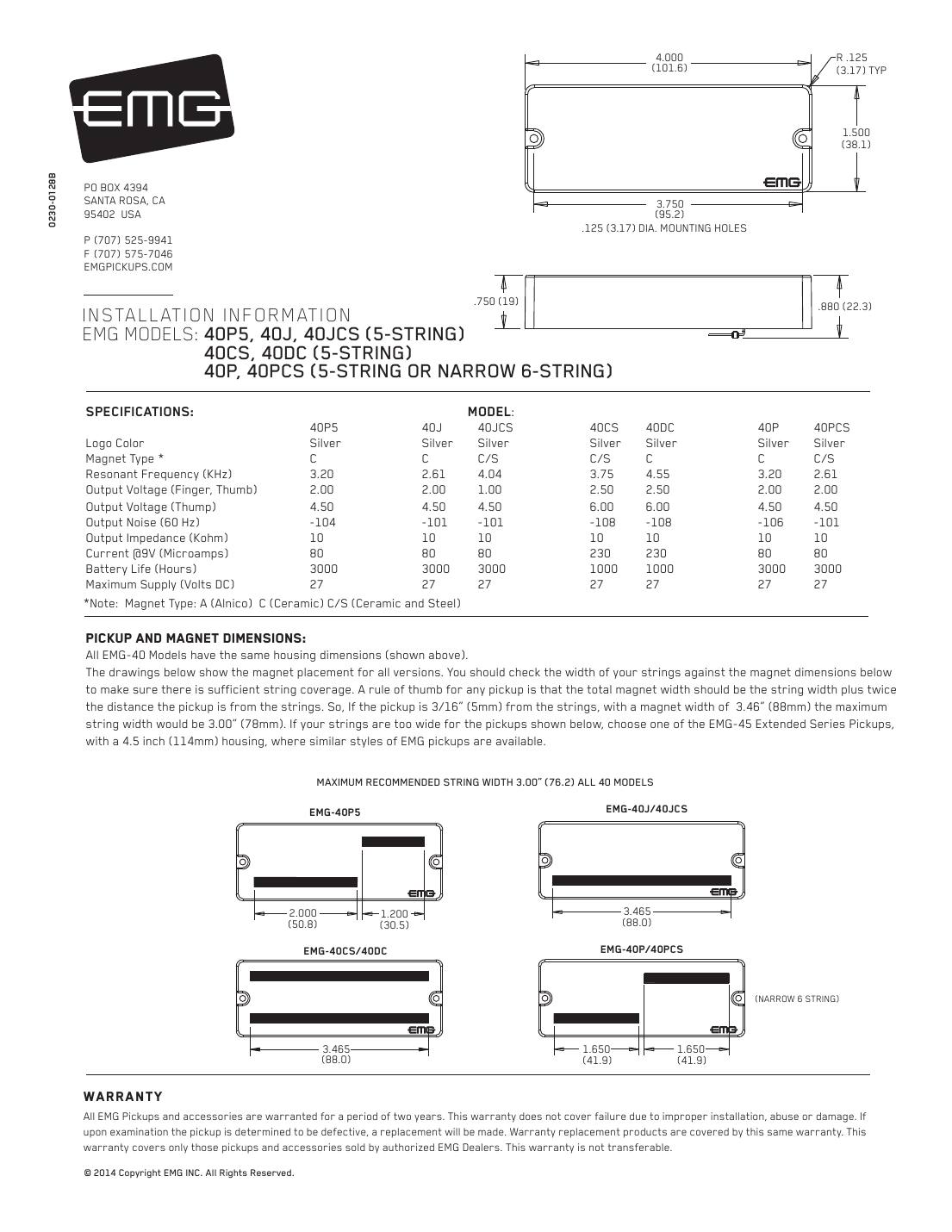
EMG's 4-inch extended housing for 5-string and narrow 6-string basses. Same solderless system and the same hookups as the 35 series.
String spread: 3.00" (76.2 mm) maximum string spread.
In the box: 25K volume and 25K tone pot, 13.5" pickup cable, 5.5" connect cables, 6" output cable, stereo output jack, battery buss, 7" battery cable, adjustment screws.
| 40P5 | 40J | 40JCS | 40CS | 40DC | 40P | 40PCS | |
|---|---|---|---|---|---|---|---|
| Logo | Silver | Silver | Silver | Silver | Silver | Silver | Silver |
| Magnet | C | C | C/S | C/S | C | C | C/S |
| Resonant frequency (kHz) | 3.20 | 2.61 | 4.04 | 3.75 | 4.55 | 3.20 | 2.61 |
| Output, finger/thumb (V) | 2.00 | 2.00 | 1.00 | 2.50 | 2.50 | 2.00 | 2.00 |
| Output, thump (V) | 4.50 | 4.50 | 4.50 | 6.00 | 6.00 | 4.50 | 4.50 |
| Noise at 60 Hz (dBV) | -104 | -101 | -101 | -108 | -108 | -106 | -101 |
| Output impedance (kΩ) | 10 | 10 | 10 | 10 | 10 | 10 | 10 |
| Current at 9 V (µA) | 80 | 80 | 80 | 230 | 230 | 80 | 80 |
| Battery life (hours) | 3000 | 3000 | 3000 | 1000 | 1000 | 3000 | 3000 |
Magnet: C = ceramic, A = alnico, C/S = ceramic and steel. Maximum supply 27 V DC.
Hookups on this sheet
- EMG active, one pickup: volume only, or volume and tone
- EMG active, two pickups: volume, volume, master tone (J-bass style)
- EMG active, two pickups with a 3-way switch (B245 pickup buss)
- EMG active, two pickups: active balance, active tone, master volume
- EMG: long panel jack, older EMGs, battery holders and 18 V
- The 40CS and 40DC draw 230 µA, so a battery lasts about 1,000 hours instead of 3,000.
EMG 45 series bass pickups: 45P, 45PCS, 45J, 45JCS, 45CS, 45DC
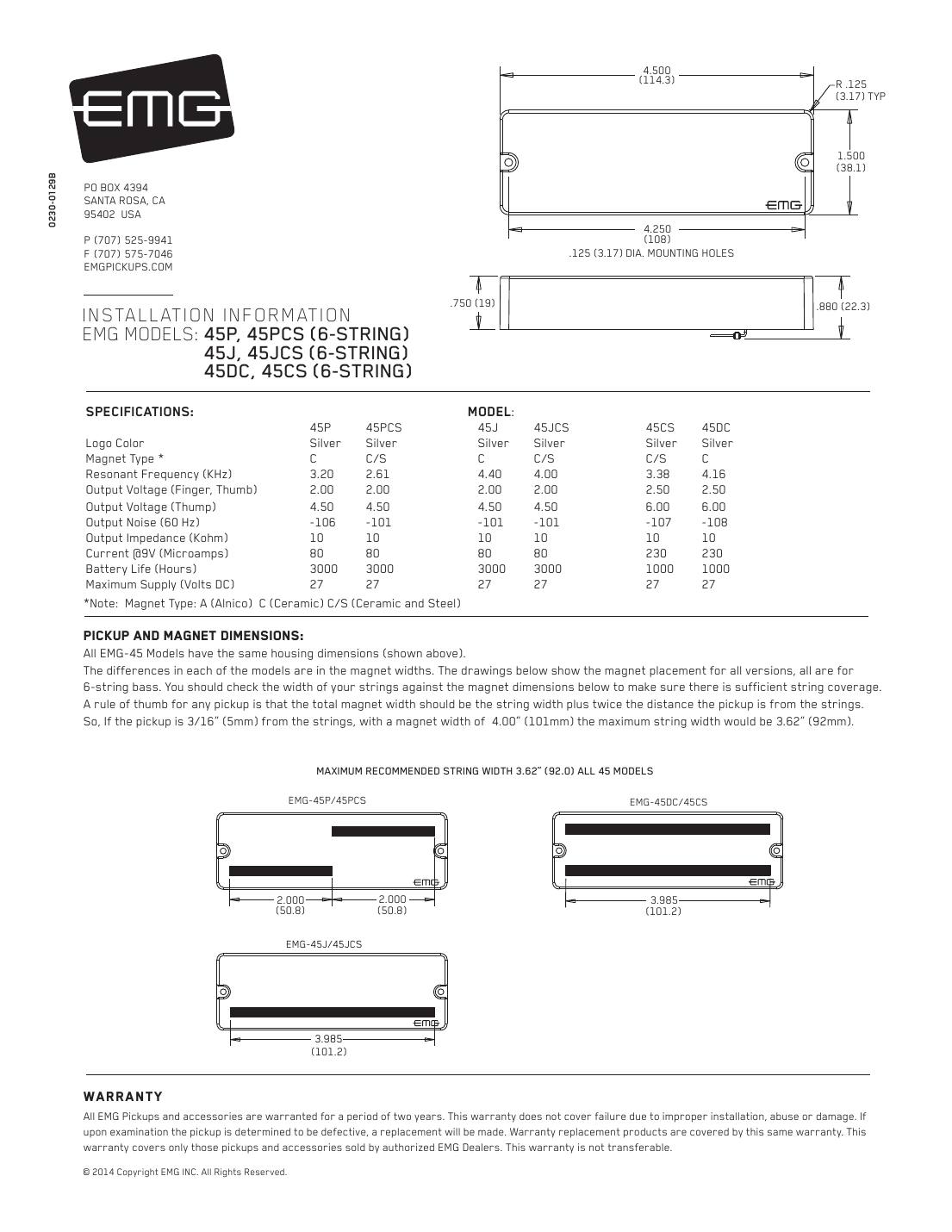
EMG's widest housing, for 6-string basses. Same solderless system and hookups as the 35 and 40 series.
String spread: 3.62" (92.0 mm) maximum string spread.
In the box: 25K volume and 25K tone pot, 13.5" pickup cable, 5.5" connect cables, 6" output cable, stereo output jack, battery buss, 7" battery cable, adjustment screws.
| 45P | 45PCS | 45J | 45JCS | 45CS | 45DC | |
|---|---|---|---|---|---|---|
| Logo | Silver | Silver | Silver | Silver | Silver | Silver |
| Magnet | C | C/S | C | C/S | C/S | C |
| Resonant frequency (kHz) | 3.20 | 2.61 | 4.40 | 4.00 | 3.38 | 4.16 |
| Output, finger/thumb (V) | 2.00 | 2.00 | 2.00 | 2.00 | 2.50 | 2.50 |
| Output, thump (V) | 4.50 | 4.50 | 4.50 | 4.50 | 6.00 | 6.00 |
| Noise at 60 Hz (dBV) | -106 | -101 | -101 | -101 | -107 | -108 |
| Output impedance (kΩ) | 10 | 10 | 10 | 10 | 10 | 10 |
| Current at 9 V (µA) | 80 | 80 | 80 | 80 | 230 | 230 |
| Battery life (hours) | 3000 | 3000 | 3000 | 3000 | 1000 | 1000 |
Magnet: C = ceramic, A = alnico, C/S = ceramic and steel. Maximum supply 27 V DC.
Hookups on this sheet
- EMG active, one pickup: volume only, or volume and tone
- EMG active, two pickups: volume, volume, master tone (J-bass style)
- EMG active, two pickups with a 3-way switch (B245 pickup buss)
- EMG active, two pickups: active balance, active tone, master volume
- EMG: long panel jack, older EMGs, battery holders and 18 V
- The 45CS and 45DC draw 230 µA, so a battery lasts about 1,000 hours.
EMG P, PA, P-CS, P5 and P6 bass pickups
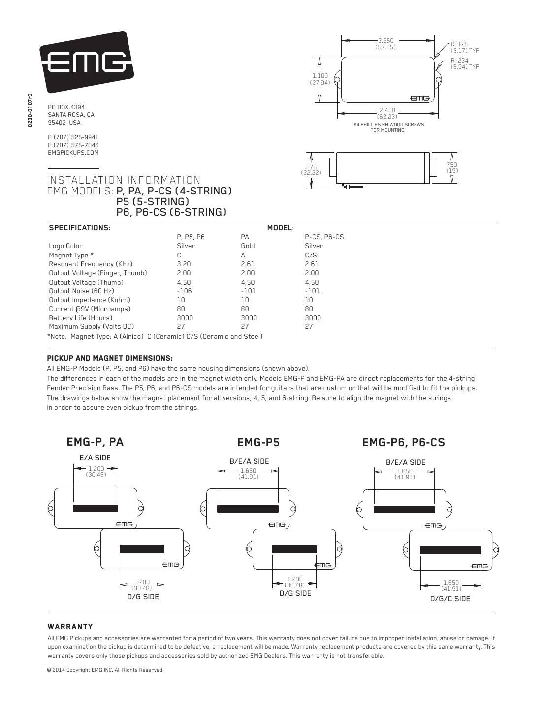
EMG's split-coil P pickups. The P and PA are direct replacements for a 4-string Precision Bass; the P5, P6 and P6-CS are for custom or modified basses. All share one housing; only the magnet width changes.
String spread: Match the magnet to the strings: P/PA for 4-string, P5 for 5-string, P6/P6-CS for 6-string.
In the box: 25K volume and 25K tone pot, 13.5" pickup cable, 5.5" connect cables, 6" output cable, stereo output jack, battery buss, 7" battery cable, 4 adjustment screws.
| P, P5, P6 | PA | P-CS, P6-CS | |
|---|---|---|---|
| Logo | Silver | Gold | Silver |
| Magnet | C | A | C/S |
| Resonant frequency (kHz) | 3.20 | 2.61 | 2.61 |
| Output, finger/thumb (V) | 2.00 | 2.00 | 2.00 |
| Output, thump (V) | 4.50 | 4.50 | 4.50 |
| Noise at 60 Hz (dBV) | -106 | -101 | -101 |
| Output impedance (kΩ) | 10 | 10 | 10 |
| Current at 9 V (µA) | 80 | 80 | 80 |
| Battery life (hours) | 3000 | 3000 | 3000 |
Magnet: C = ceramic, A = alnico, C/S = ceramic and steel. Maximum supply 27 V DC.
Hookups on this sheet
- EMG active, one pickup: volume only, or volume and tone
- EMG active, two pickups: volume, volume, master tone (J-bass style)
- EMG active, two pickups with a 3-way switch (B245 pickup buss)
- EMG active, two pickups: active balance, active tone, master volume
- EMG: long panel jack, older EMGs, battery holders and 18 V
- Sheet diagram #5 (balance control): the text says B125, but the drawing is labelled B118. Either EMG active balance control is wired the same way.
- The library labels this sheet 'P (4-string), PA, P-CS, P5, P6, P6-CS'; the sheet itself lists P, PA-V1, PA-V2 and P-CS.
EMG TB series bass pickups: TBP, TBPA, TBP5, TBJ, TBJA, TBCS, TBDC
EMG's TB housing (the Thunderbird-style bass shape). All TB models share one housing; the magnets differ.
String spread: 2.50" (63.5 mm) maximum string spread.
In the box: 25K volume and 25K tone pot, 13.5" pickup cable, 5.5" connect cables, 6" output cable, stereo output jack, battery buss, 7" battery cable, adjustment screws.
| TBP | TBPA | TBJ | TBJA | TBP5 | TBCS | TBDC | |
|---|---|---|---|---|---|---|---|
| Logo | Silver | Gold | Silver | Gold | Silver | Silver | Silver |
| Magnet | C | A | C | A | C | C/S | C |
| Resonant frequency (kHz) | 3.20 | 2.61 | 3.95 | 3.20 | 3.20 | 3.95 | 4.85 |
| Output, finger/thumb (V) | 2.00 | 2.00 | 2.00 | 1.50 | 2.00 | 2.00 | 2.00 |
| Output, thump (V) | 4.50 | 4.50 | 4.50 | 4.50 | 4.50 | 6.00 | 6.00 |
| Noise at 60 Hz (dBV) | -106 | -101 | -101 | -99 | -106 | -109 | -107 |
| Output impedance (kΩ) | 10 | 10 | 10 | 10 | 10 | 10 | 10 |
| Current at 9 V (µA) | 80 | 80 | 80 | 80 | 80 | 235 | 235 |
| Battery life (hours) | 3000 | 3000 | 3000 | 3000 | 3000 | 3000 | 3000 |
Magnet: C = ceramic, A = alnico, C/S = ceramic and steel. Maximum supply 27 V DC.
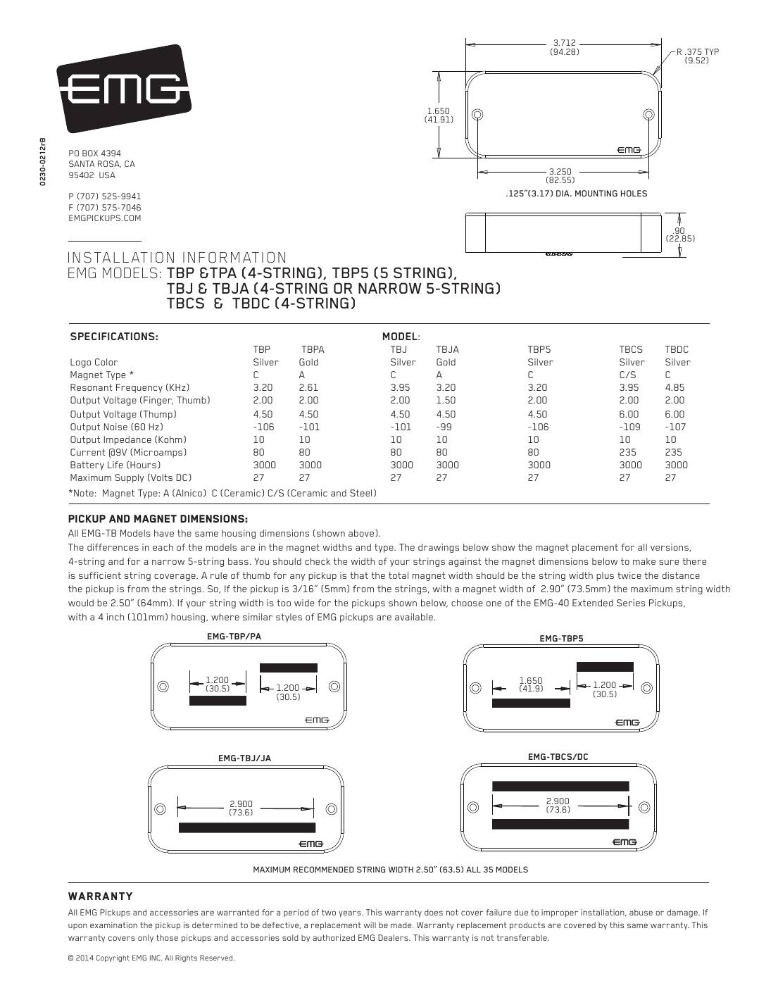
Hookups on this sheet
- EMG active, one pickup: volume only, or volume and tone
- EMG active, two pickups: volume, volume, master tone (J-bass style)
- EMG active, two pickups with a 3-way switch (B245 pickup buss)
- EMG active, two pickups: active balance, active tone, master volume
- EMG: long panel jack, older EMGs, battery holders and 18 V
- The library lists 'TPA'; EMG's sheet calls it TBPA.
EMG MMCS (Music Man 4-string replacement)
A direct replacement for the 4-string Music Man pickup, with a 0.950-inch aperture for high output and a ceramic-and-steel design for a milder attack.
String spread: 2.50" (63.5 mm) maximum string spread.
In the box: 25K volume and 25K tone pot, 13.5" pickup cable, 5.5" connect cables, 6" output cable, stereo output jack, battery buss, 7" battery cable, 3 adjustment screws.
| MMCS | |
|---|---|
| Logo | Silver |
| Magnet | C/S |
| Resonant frequency (kHz) | 2.50 |
| Output, finger/thumb (V) | 2.00 |
| Output, thump (V) | 4.50 |
| Noise at 60 Hz (dBV) | -107 |
| Output impedance (kΩ) | 10 |
| Current at 9 V (µA) | 80 |
| Battery life (hours) | 3000 |
Magnet: C = ceramic, A = alnico, C/S = ceramic and steel. Maximum supply 27 V DC.
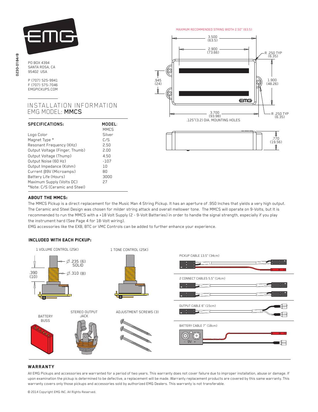
Hookups on this sheet
- EMG active, one pickup: volume only, or volume and tone
- EMG active, two pickups: volume, volume, master tone (J-bass style)
- EMG active, two pickups with a 3-way switch (B245 pickup buss)
- EMG active, two pickups: active balance, active tone, master volume
- EMG: long panel jack, older EMGs, battery holders and 18 V
- EMG recommends running the MMCS at 18 V (two 9 V batteries) to handle its output, especially if you play hard. It works on 9 V. See the 18 V hookup below.
EMG MM5CS (Music Man 5-string replacement)
The 5-string version of the MMCS: a direct replacement for the 5-string Music Man pickup, 0.950-inch aperture, ceramic and steel.
String spread: 3.08" (78.2 mm) maximum string spread.
In the box: 25K volume and 25K tone pot, 13.5" pickup cable, 5.5" connect cables, 6" output cable, stereo output jack, battery buss, 7" battery cable, 3 adjustment screws.
| MM5CS | |
|---|---|
| Logo | Silver |
| Magnet | C/S |
| Resonant frequency (kHz) | 2.50 |
| Output, finger/thumb (V) | 2.00 |
| Output, thump (V) | 4.50 |
| Noise at 60 Hz (dBV) | -107 |
| Output impedance (kΩ) | 10 |
| Current at 9 V (µA) | 80 |
| Battery life (hours) | 3000 |
Magnet: C = ceramic, A = alnico, C/S = ceramic and steel. Maximum supply 27 V DC.
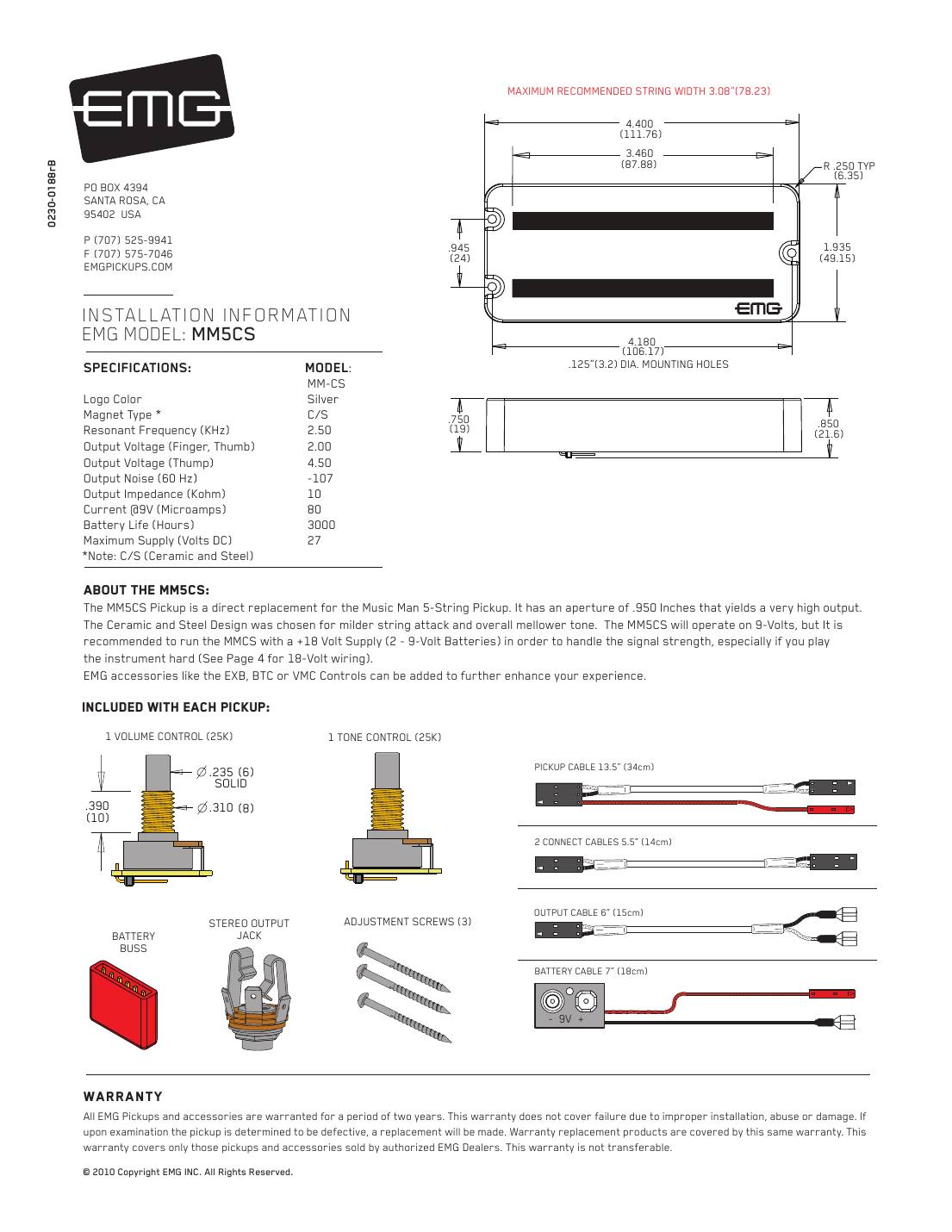
Hookups on this sheet
- EMG active, one pickup: volume only, or volume and tone
- EMG active, two pickups: volume, volume, master tone (J-bass style)
- EMG active, two pickups with a 3-way switch (B245 pickup buss)
- EMG active, two pickups: active balance, active tone, master volume
- EMG: long panel jack, older EMGs, battery holders and 18 V
- As with the MMCS, EMG recommends 18 V for the MM5CS.
EMG HB (bass pickup in a guitar humbucker housing)
A bass pickup in a standard guitar humbucker housing, for narrow 4-string basses only.
String spread: 2.10" maximum string spread.
In the box: 25K volume and 25K tone pot, 15" pickup cable, 6" output cable, stereo output jack, battery buss, 7" battery cable, adjustment screws and springs.
| HB | |
|---|---|
| Logo | Silver |
| Magnet | C/S |
| Resonant frequency (kHz) | 3.20 |
| Output, finger/thumb (V) | 2.00 |
| Output, thump (V) | 4.50 |
| Noise at 60 Hz (dBV) | -106 |
| Output impedance (kΩ) | 10 |
| Current at 9 V (µA) | 80 |
| Battery life (hours) | 3000 |
Magnet: C = ceramic, A = alnico, C/S = ceramic and steel. Maximum supply 27 V DC.
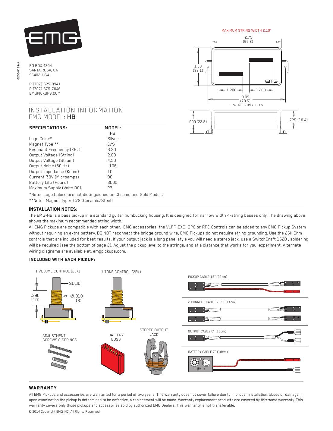
Hookups on this sheet
- EMG active, one pickup: volume only, or volume and tone
- EMG active, two pickups: volume, volume, master tone (J-bass style)
- EMG active, two pickups with a 3-way switch (B245 pickup buss)
- EMG active, two pickups: active balance, active tone, master volume
- EMG: long panel jack, older EMGs, battery holders and 18 V
- EMG: do not reconnect the bridge ground wire, and use the 25K controls that come with the pickup.
- Chrome and gold HB covers don't show a logo colour.
EMG LJ (single long J pickup, 4 or 5-string)
A single long-housing J pickup, sold on its own for the bridge position or as a replacement.
String spread: 2.725" (69.2 mm) maximum string spread.
In the box: 25K volume and 25K tone pot, 13.5" pickup cable, 6" output cable, stereo output jack, battery buss, 7" battery cable, 4 adjustment screws.
| LJ | |
|---|---|
| Logo | Silver |
| Magnet | C |
| Resonant frequency (kHz) | 3.95 |
| Output, finger/thumb (V) | 2.00 |
| Output, thump (V) | 4.50 |
| Noise at 60 Hz (dBV) | -102 |
| Output impedance (kΩ) | 10 |
| Current at 9 V (µA) | 80 |
| Battery life (hours) | 3000 |
Magnet: C = ceramic, A = alnico, C/S = ceramic and steel. Maximum supply 27 V DC.
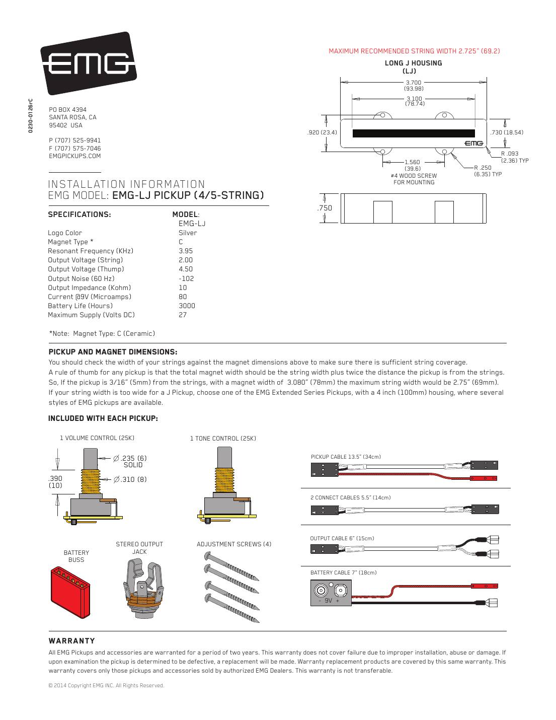
Hookups on this sheet
- EMG active, one pickup: volume only, or volume and tone
- EMG active, two pickups: volume, volume, master tone (J-bass style)
- EMG active, two pickups with a 3-way switch (B245 pickup buss)
- EMG active, two pickups: active balance, active tone, master volume
- EMG: long panel jack, older EMGs, battery holders and 18 V
EMG LJV (vintage-voiced long J pickup, 4-string)
A long J pickup with EMG's JV preamp: voiced like a vintage passive J, less hot and with a smoother attack. EMG says it is typically paired with an EMG-P in a PJ bass.
String spread: 4-string.
In the box: 25K volume and 25K tone pot, 13.5" pickup cable, 6" output cable, stereo output jack, battery buss, 7" battery cable, 4 adjustment screws.
| LJV | |
|---|---|
| Logo | Gold |
| Magnet | Alnico 5 |
| Resonant frequency (kHz) | 3.20 |
| Output, finger/thumb (V) | 1.50 |
| Output, thump (V) | 4.50 |
| Noise at 60 Hz (dBV) | -99 |
| Output impedance (kΩ) | 10 |
| Current at 9 V (µA) | 80 |
| Battery life (hours) | 3000 |
Magnet: C = ceramic, A = alnico, C/S = ceramic and steel. Maximum supply 27 V DC.
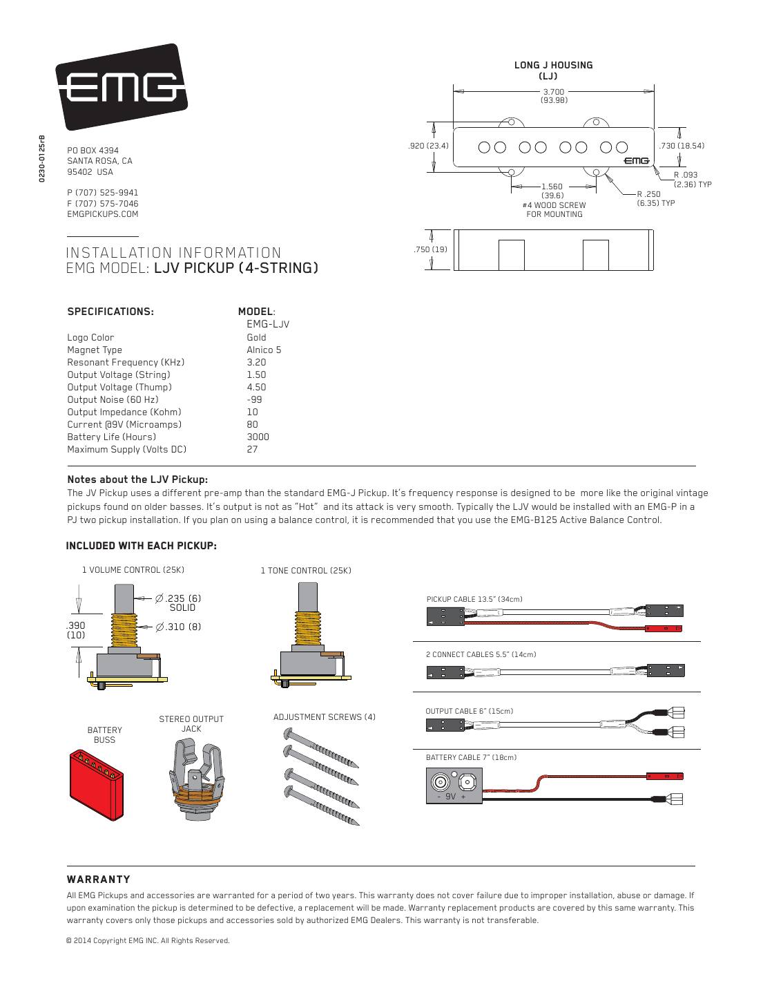
Hookups on this sheet
- EMG active, one pickup: volume only, or volume and tone
- EMG active, two pickups: volume, volume, master tone (J-bass style)
- EMG active, two pickups with a 3-way switch (B245 pickup buss)
- EMG active, two pickups: active balance, active tone, master volume
- EMG: long panel jack, older EMGs, battery holders and 18 V
- With a balance control, EMG recommends its B125 active balance control (buffered inputs) for JV pickups.
EMG JV set (vintage-voiced J pair)
A short (neck) and long (bridge) J pair with EMG's vintage-voiced JV preamp: less output than a standard EMG J and a smoother attack.
String spread: 4-string; short housing (SJ) at the neck, long housing (LJ) at the bridge.
In the box: Two volumes and a tone (25K), 13.5" and 9" pickup cables, connect cables, 6" output cable, stereo output jack, battery buss, 7" battery cable, 8 adjustment screws.
| JV set | |
|---|---|
| Logo | Gold |
| Magnet | Alnico 5 |
| Resonant frequency (kHz) | 3.20 |
| Output, finger/thumb (V) | 1.50 |
| Output, thump (V) | 4.50 |
| Noise at 60 Hz (dBV) | -99 |
| Output impedance (kΩ) | 10 |
| Current at 9 V (µA) | 80 |
| Battery life (hours) | 3000 |
Magnet: C = ceramic, A = alnico, C/S = ceramic and steel. Maximum supply 27 V DC.
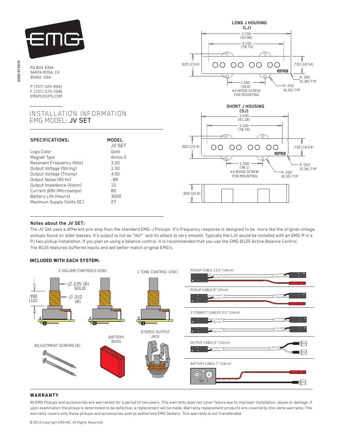
Hookups on this sheet
- EMG active, one pickup: volume only, or volume and tone
- EMG active, two pickups: volume, volume, master tone (J-bass style)
- EMG active, two pickups with a 3-way switch (B245 pickup buss)
- EMG active, two pickups: active balance, active tone, master volume
- EMG: long panel jack, older EMGs, battery holders and 18 V
- EMG recommends the B125 active balance control if you use a balance pot with JV pickups.
EMG J5, J5A and J5-CS sets (5-string J)
5-string J pairs: short housing (SJ5) at the neck, long (LJ5) at the bridge. EMG says both housings also work on 4-string basses if the magnets cover the strings.
String spread: 3.48" (88.4) magnet width for both SJ5 and LJ5: about 3.10" (79 mm) maximum string spread with the pickup 3/16" from the strings.
In the box: Two volumes and a tone (25K), 13.5" and 9" pickup cables, connect cables, 6" output cable, stereo output jack, battery buss, 7" battery cable, 8 adjustment screws.
| J5 | J5A | J5-CS | |
|---|---|---|---|
| Logo | Silver | Gold | Silver |
| Magnet | C | A | C/S |
| Resonant frequency (kHz) | 3.95 | 3.20 | 3.20 |
| Output, finger/thumb (V) | 1.00 | 1.00 | 1.00 |
| Output, thump (V) | 4.50 | 4.50 | 4.50 |
| Noise at 60 Hz (dBV) | -101 | -99 | -99 |
| Output impedance (kΩ) | 10 | 10 | 10 |
| Current at 9 V (µA) | 80 | 80 | 80 |
| Battery life (hours) | 3000 | 3000 | 3000 |
Magnet: C = ceramic, A = alnico, C/S = ceramic and steel. Maximum supply 27 V DC.
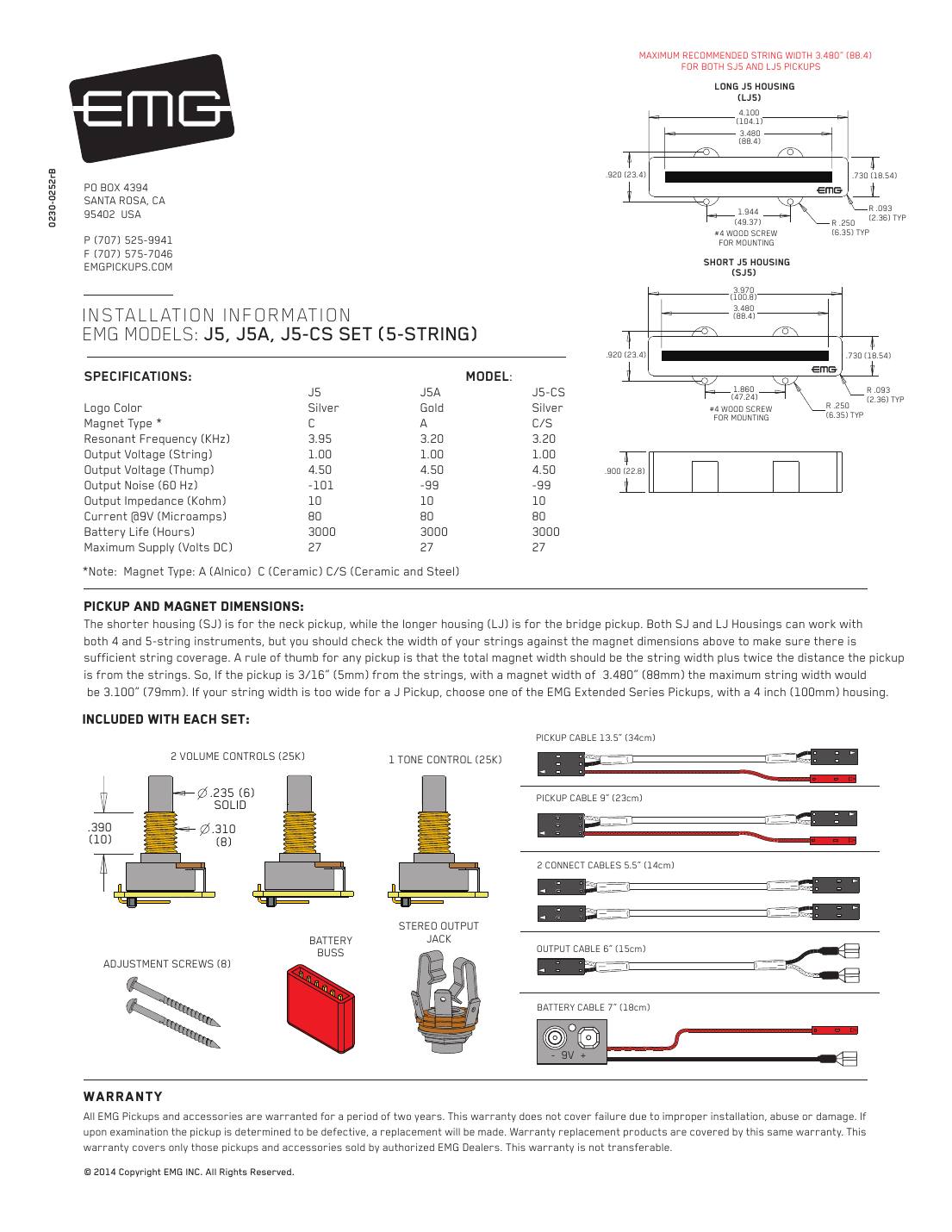
Hookups on this sheet
- EMG active, one pickup: volume only, or volume and tone
- EMG active, two pickups: volume, volume, master tone (J-bass style)
- EMG active, two pickups with a 3-way switch (B245 pickup buss)
- EMG active, two pickups: active balance, active tone, master volume
- EMG: long panel jack, older EMGs, battery holders and 18 V
X series (VLPF active tone)
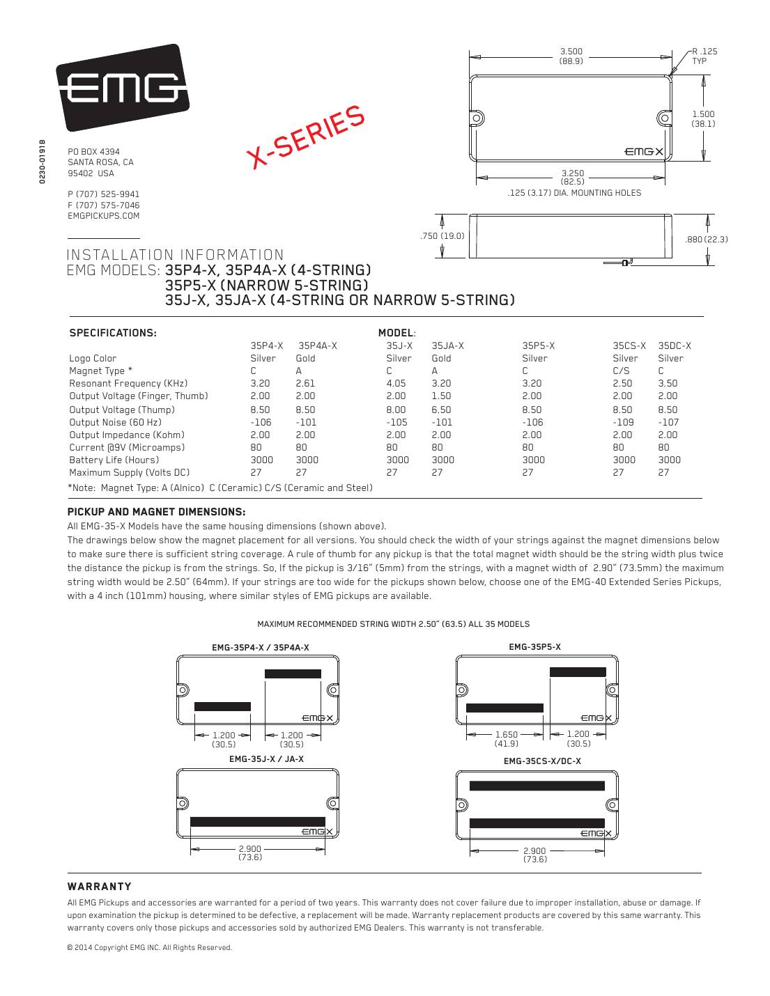
EMG 35-X series bass pickups: 35P4-X, 35P4A-X, 35P5-X, 35J-X, 35JA-X
The X versions of the 35 series: same 3.5-inch housing, more headroom (2K output impedance, up to 8.5 V on hard thumb). The big wiring difference is the tone control: X pickups ship with the VLPF active tone instead of a passive 25K tone pot.
String spread: 2.50" (63.5 mm) maximum string spread.
In the box: 25K volume, VLPF active tone control, 13.5" pickup cable, 5.5" connect cables, 6" output cable, 5.5" supply cable (VLPF power), stereo output jack, battery buss, 7" battery cable, adjustment screws.
| 35P4-X | 35P4A-X | 35J-X | 35JA-X | 35P5-X | 35CS-X | 35DC-X | |
|---|---|---|---|---|---|---|---|
| Logo | Silver | Gold | Silver | Gold | Silver | Silver | Silver |
| Magnet | C | A | C | A | C | C/S | C |
| Resonant frequency (kHz) | 3.20 | 2.61 | 4.05 | 3.20 | 3.20 | 2.50 | 3.50 |
| Output, finger/thumb (V) | 2.00 | 2.00 | 2.00 | 1.50 | 2.00 | 2.00 | 2.00 |
| Output, thump (V) | 8.50 | 8.50 | 8.00 | 6.50 | 8.50 | 8.50 | 8.50 |
| Noise at 60 Hz (dBV) | -106 | -101 | -105 | -101 | -106 | -109 | -107 |
| Output impedance (kΩ) | 2 | 2 | 2 | 2 | 2 | 2 | 2 |
| Current at 9 V (µA) | 80 | 80 | 80 | 80 | 80 | 80 | 80 |
| Battery life (hours) | 3000 | 3000 | 3000 | 3000 | 3000 | 3000 | 3000 |
Magnet: C = ceramic, A = alnico, C/S = ceramic and steel. Maximum supply 27 V DC.
Hookups on this sheet
- EMG X series: volume with the VLPF active tone
- EMG active, two pickups with a 3-way switch (B245 pickup buss)
- EMG active, two pickups: active balance, active tone, master volume
- EMG: long panel jack, older EMGs, battery holders and 18 V
- The library links two revisions of this sheet (0230-0191A and 0230-0191B). The wiring is the same; this section covers both.
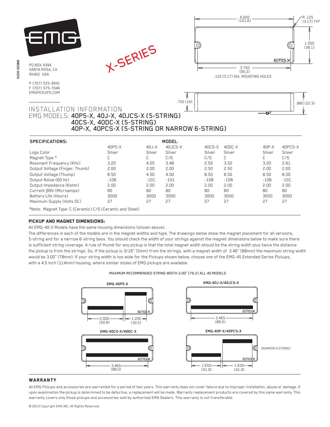
EMG 40-X series bass pickups: 40P5-X, 40J-X, 40JCS-X, 40CS-X, 40DC-X, 40P-X, 40PCS-X
X versions of the 40 series (4-inch housing, 5-string and narrow 6-string). Wired like the other X pickups: volume into the VLPF active tone.
String spread: 3.00" (76.2 mm) maximum string spread.
In the box: 25K volume, VLPF active tone, 13.5" pickup cable, 5.5" connect cables, 6" output cable, 5.5" supply cable, stereo output jack, battery buss, 7" battery cable, adjustment screws.
| 40P5-X | 40J-X | 40JCS-X | 40CS-X | 40DC-X | 40P-X | 40PCS-X | |
|---|---|---|---|---|---|---|---|
| Logo | Silver | Silver | Silver | Silver | Silver | Silver | Silver |
| Magnet | C | C | C/S | C/S | C | C | C/S |
| Resonant frequency (kHz) | 3.20 | 4.05 | 3.48 | 2.50 | 3.50 | 3.20 | 2.61 |
| Output, finger/thumb (V) | 2.00 | 2.00 | 2.00 | 2.50 | 2.50 | 2.00 | 2.00 |
| Output, thump (V) | 8.50 | 4.50 | 4.50 | 8.50 | 8.50 | 8.50 | 8.50 |
| Noise at 60 Hz (dBV) | -106 | -101 | -101 | -108 | -108 | -106 | -101 |
| Output impedance (kΩ) | 2 | 2 | 2 | 2 | 2 | 2 | 2 |
| Current at 9 V (µA) | 80 | 80 | 80 | 80 | 80 | 80 | 80 |
| Battery life (hours) | 3000 | 3000 | 3000 | 3000 | 3000 | 3000 | 3000 |
Magnet: C = ceramic, A = alnico, C/S = ceramic and steel. Maximum supply 27 V DC.
Hookups on this sheet
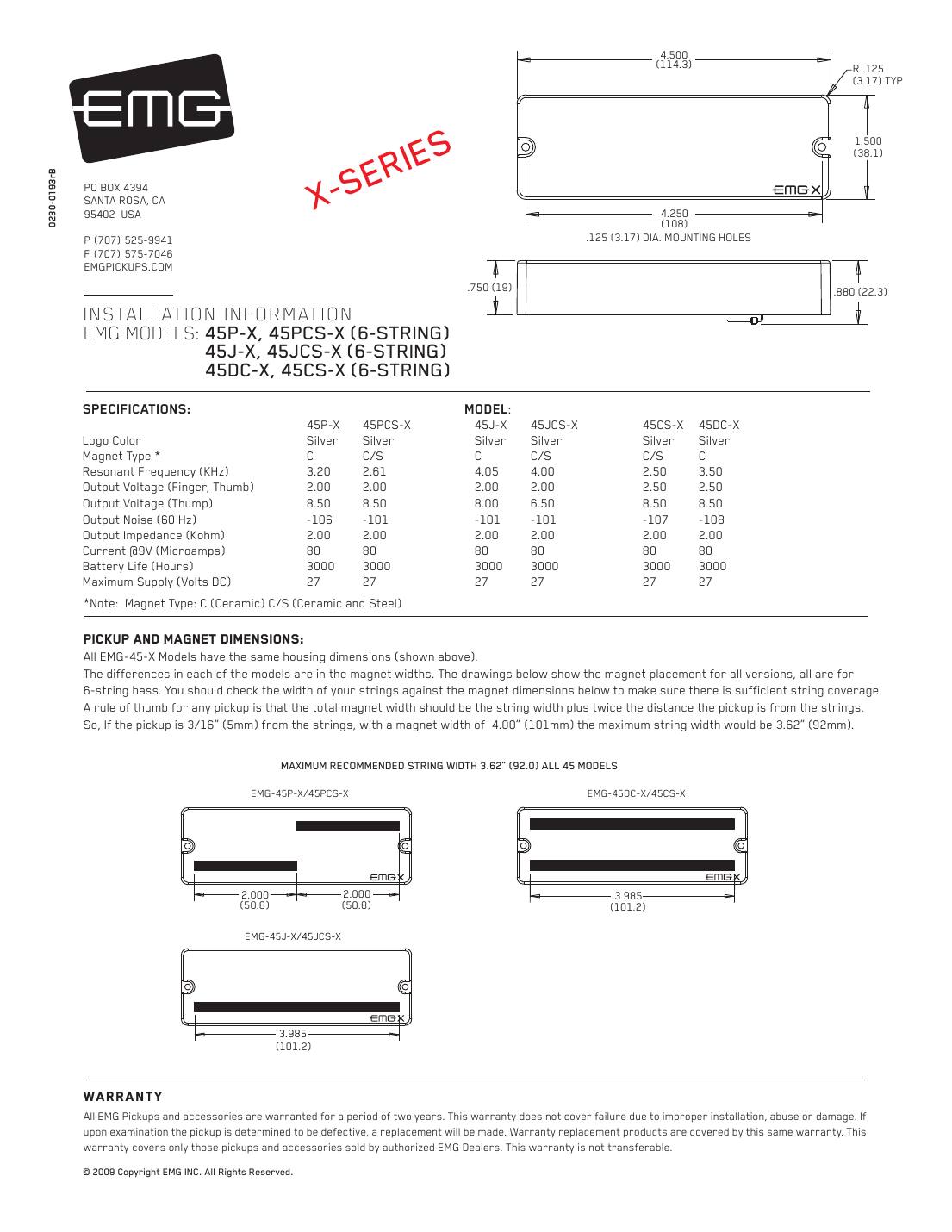
EMG 45-X series bass pickups: 45P-X, 45PCS-X, 45J-X, 45JCS-X, 45CS-X, 45DC-X
X versions of the 6-string 45 series, wired with the VLPF active tone.
String spread: 3.62" (92.0 mm) maximum string spread.
In the box: 25K volume, VLPF active tone, 13.5" pickup cable, 5.5" connect cables, 6" output cable, 5.5" supply cable, stereo output jack, battery buss, 7" battery cable, adjustment screws.
| 45P-X | 45PCS-X | 45J-X | 45JCS-X | 45CS-X | 45DC-X | |
|---|---|---|---|---|---|---|
| Logo | Silver | Silver | Silver | Silver | Silver | Silver |
| Magnet | C | C/S | C | C/S | C/S | C |
| Resonant frequency (kHz) | 3.20 | 2.61 | 4.05 | 4.00 | 2.50 | 3.50 |
| Output, finger/thumb (V) | 2.00 | 2.00 | 2.00 | 2.00 | 2.50 | 2.50 |
| Output, thump (V) | 8.50 | 8.50 | 8.00 | 6.50 | 8.50 | 8.50 |
| Noise at 60 Hz (dBV) | -106 | -101 | -101 | -101 | -107 | -108 |
| Output impedance (kΩ) | 2 | 2 | 2 | 2 | 2 | 2 |
| Current at 9 V (µA) | 80 | 80 | 80 | 80 | 80 | 80 |
| Battery life (hours) | 3000 | 3000 | 3000 | 3000 | 3000 | 3000 |
Magnet: C = ceramic, A = alnico, C/S = ceramic and steel. Maximum supply 27 V DC.
Hookups on this sheet
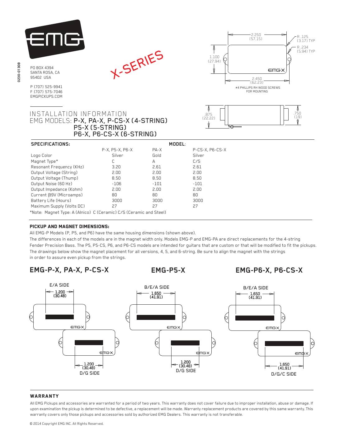
EMG P-X, PA-X, P-CS-X, P5-X and P6-X bass pickups
X versions of the EMG P family, wired with the VLPF active tone.
String spread: Match the magnet to the strings: P-X/PA-X for 4-string, P5-X for 5-string, P6-X/P6-CS-X for 6-string.
In the box: 25K volume, VLPF active tone, 13.5" pickup cable, 5.5" connect cables, 6" output cable, 5.5" supply cable, stereo output jack, battery buss, 7" battery cable, 4 adjustment screws.
| P-X, P5-X, P6-X | PA-X | P-CS-X, P6-CS-X | |
|---|---|---|---|
| Logo | Silver | Gold | Silver |
| Magnet | C | A | C/S |
| Resonant frequency (kHz) | 3.20 | 2.61 | 2.61 |
| Output, finger/thumb (V) | 2.00 | 2.00 | 2.00 |
| Output, thump (V) | 8.50 | 8.50 | 8.50 |
| Noise at 60 Hz (dBV) | -106 | -101 | -101 |
| Output impedance (kΩ) | 2 | 2 | 2 |
| Current at 9 V (µA) | 80 | 80 | 80 |
| Battery life (hours) | 3000 | 3000 | 3000 |
Magnet: C = ceramic, A = alnico, C/S = ceramic and steel. Maximum supply 27 V DC.
Hookups on this sheet
EMG JV-X set (4-string)
The X version of the JV pair, wired with the VLPF active tone. Short housing (SJ) at the neck, long (LJ) at the bridge; each has its own magnet layout.
String spread: 4-string.
In the box: 25K volumes, VLPF active tone, 13.5" and 9" pickup cables, 3 connect cables, 5.5" supply cable, 6" output cable, stereo output jack, battery buss, 7" battery cable, 8 adjustment screws.
| JV-X | |
|---|---|
| Logo | Silver |
| Magnet | Alnico 5 |
| Resonant frequency (kHz) | 3.20 |
| Output, finger/thumb (V) | 2.00 |
| Output, thump (V) | 8.00 |
| Noise at 60 Hz (dBV) | -99 |
| Output impedance (kΩ) | 2 |
| Current at 9 V (µA) | 80 |
| Battery life (hours) | 3000 |
Magnet: C = ceramic, A = alnico, C/S = ceramic and steel. Maximum supply 27 V DC.
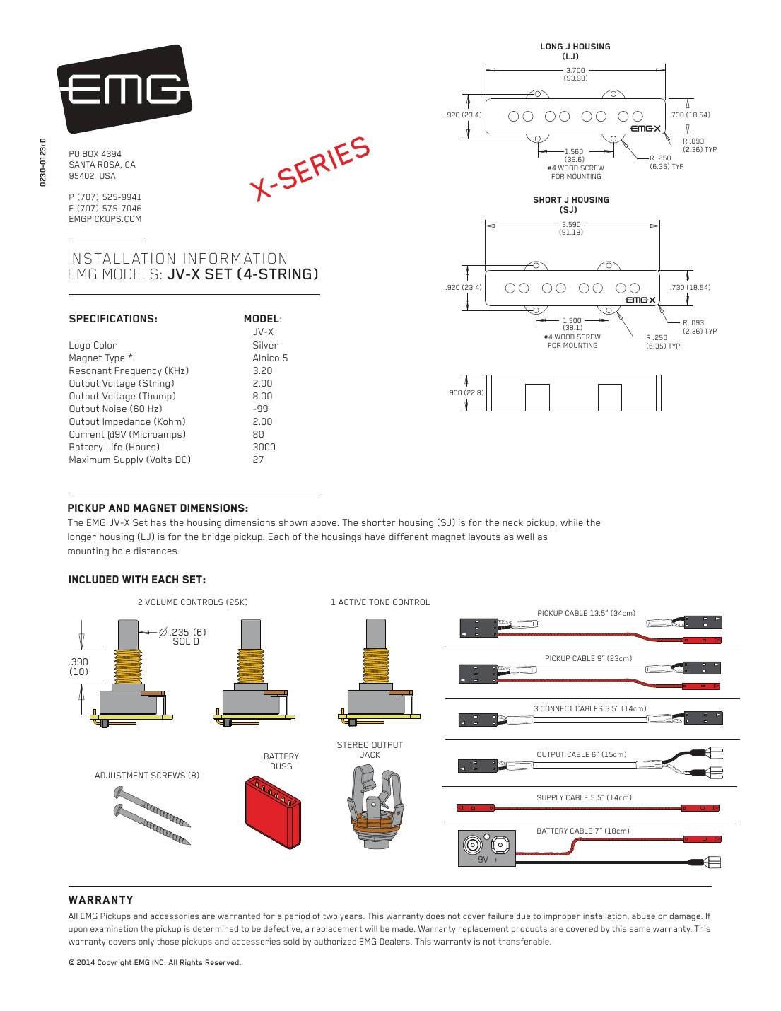
Hookups on this sheet
- EMG X series: volume with the VLPF active tone
- EMG active, two pickups with a 3-way switch (B245 pickup buss)
- EMG active, two pickups: active balance, active tone, master volume
- EMG: long panel jack, older EMGs, battery holders and 18 V
- The sheet's balance-control drawing uses the B118 active balance control.
- With a toggle switch, this sheet runs the B245 buss output into the active tone first (reversed connector on pins 1 and 2), then the master volume, then the jack.
J systems with a pre-wired control board
EMG J, JA and J-CS system (pre-wired control plate)
A drop-in Jazz Bass system: the J pair plus a complete volume/volume/tone set built on one circuit board, so the pickups, output cable and battery all plug into the board.
String spread: 4 or 5-string; short housing (SJ) at the neck, long (LJ) at the bridge, with different mounting-hole spacing.
In the box: SJ and LJ pickups with cables, pre-wired volume/volume/tone control board, output cable, stereo jack, battery clip.
| J | JA | J-CS | |
|---|---|---|---|
| Logo | Silver | Gold | Silver |
| Magnet | C | A | C/S |
| Resonant frequency (kHz) | 3.95 | 3.20 | 3.20 |
| Output, finger/thumb (V) | 2.00 | 1.00 | 1.00 |
| Output, thump (V) | 4.50 | 4.50 | 4.50 |
| Noise at 60 Hz (dBV) | -101 | -99 | -99 |
| Output impedance (kΩ) | 10 | 10 | 10 |
| Current at 9 V (µA) | 80 | 80 | 80 |
| Battery life (hours) | 3000 | 3000 | 3000 |
Magnet: C = ceramic, A = alnico, C/S = ceramic and steel. Maximum supply 27 V DC.
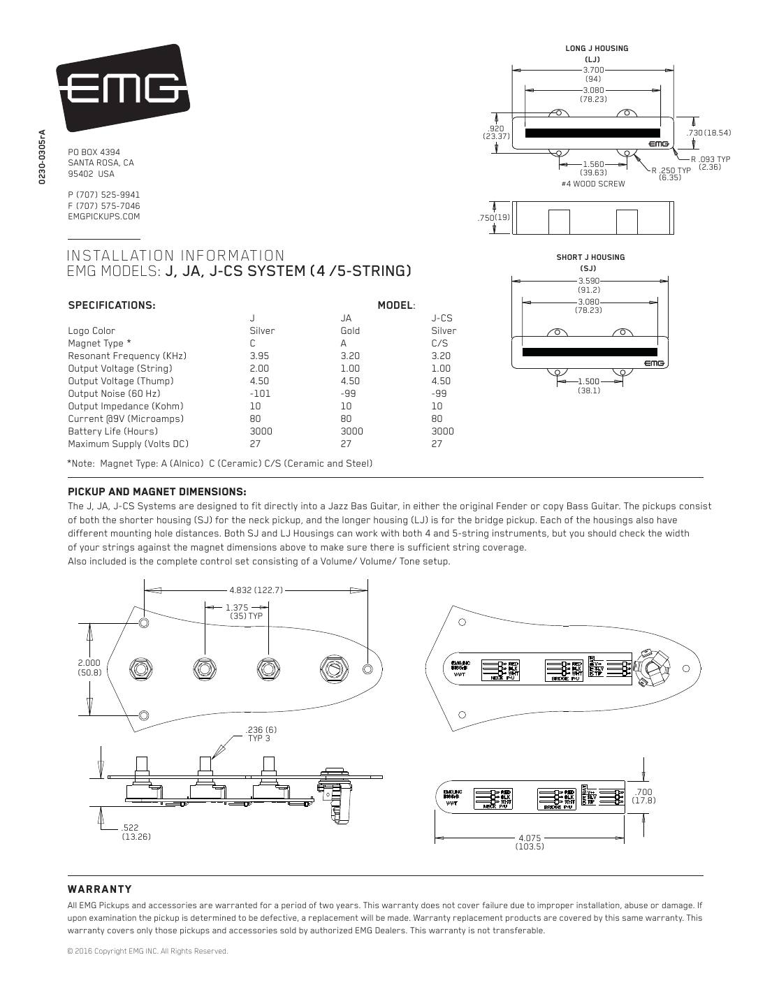
Hookups on this sheet
- EMG J system: plugging into the pre-wired control board
- EMG: long panel jack, older EMGs, battery holders and 18 V
- The separately boxed EMG J set, with individual solderless pots and the B157 selector buss, is covered on our EMG J, JA and J-CS wiring page.
- EMG warns the battery may not fit the original control cavity: check before you start, and consider a separate battery box on the back of the bass.
- Cut the bridge ground wire; it is not reconnected.
EMG J-X, JA-X and J-CS-X system (pre-wired control plate)
The X version of the drop-in J system: X pickups plus the pre-wired control board. Installation is the same as the J system above.
String spread: 4 or 5-string; short housing (SJ) at the neck, long (LJ) at the bridge.
In the box: SJ-X and LJ-X pickups with cables, pre-wired control board, output cable, stereo jack, battery clip.
| J-X | JA-X | J-CS-X | |
|---|---|---|---|
| Logo | Silver | Gold | Silver |
| Magnet | C | A | C/S |
| Resonant frequency (kHz) | 4.05 | 3.48 | 3.48 |
| Output, finger/thumb (V) | 2.00 | 1.75 | 1.75 |
| Output, thump (V) | 8.00 | 6.50 | 6.50 |
| Noise at 60 Hz (dBV) | -105 | -101 | -101 |
| Output impedance (kΩ) | 2 | 2 | 2 |
| Current at 9 V (µA) | 80 | 80 | 80 |
| Battery life (hours) | 3000 | 3000 | 3000 |
Magnet: C = ceramic, A = alnico, C/S = ceramic and steel. Maximum supply 27 V DC.
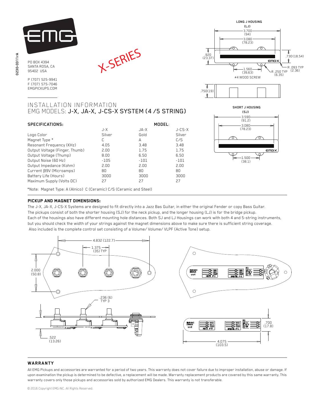
Hookups on this sheet
- EMG J system: plugging into the pre-wired control board
- EMG: long panel jack, older EMGs, battery holders and 18 V
- Cut the bridge ground wire; EMG active pickups don't need it.
TW dual-mode pickups (push-pull coil switch)
EMG 35-TW (dual-mode, 35 housing)
EMG's TW pickups have three coils and switch between a dual-coil (humbucking) sound and a single-coil sound with the supplied push-pull pot. The 35-TW fits the 35 soapbar housing.
String spread: 2.50" (63.5 mm) maximum string spread.
In the box: TW push-pull pot (25K) with plug-on circuit board, 25K tone pot, 15" TW pickup cable, 5.5" connect cables, 6" output cable, stereo output jack, battery buss, 7" battery cable, adjustment screws.
| Single coil | Dual coil | |
|---|---|---|
| Resonant frequency (kHz) | 5.40 | 2.50 |
| Output, finger (V) | 1.00 | 2.00 |
| Output, thump (V) | 3.00 | 4.50 |
| Noise at 60 Hz (dBV) | -107 | -109 |
| Output impedance (kΩ) | 10 | 10 |
Current: 160 µA at 9 V, about 1,500 hours per battery. Maximum supply 27 V.
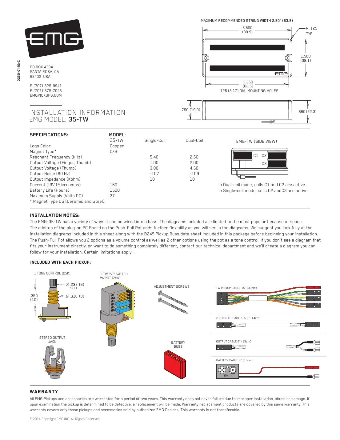
Hookups on this sheet
- EMG TW pickups: setting the push-pull coil switch
- EMG TW push-pull pot: four ways to use the 25K pot
- EMG TW: one or two TW pickups, complete hookups
- EMG: long panel jack, older EMGs, battery holders and 18 V
- Coils: dual-coil mode uses C1 and C2; single-coil mode uses C2 and C3. Ceramic and steel magnets.
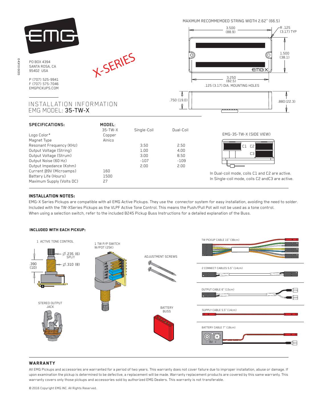
EMG 35-TW-X (dual-mode, X series)
The X version of the 35-TW: alnico magnets, 2K output impedance and more headroom. Same push-pull options as the 35-TW.
String spread: 2.62" (66.5 mm) maximum string spread.
In the box: TW push-pull pot (25K) with plug-on circuit board, 25K tone pot, 15" TW pickup cable, 5.5" connect cables, 6" output cable, stereo output jack, battery buss, 7" battery cable, adjustment screws. X versions add a 5.5" supply cable.
| Single coil | Dual coil | |
|---|---|---|
| Resonant frequency (kHz) | 3.50 | 2.50 |
| Output, finger (V) | 1.00 | 4.00 |
| Output, thump (V) | 3.00 | 8.50 |
| Noise at 60 Hz (dBV) | -107 | -109 |
| Output impedance (kΩ) | 2 | 2 |
Current: 160 µA at 9 V, about 1,500 hours per battery. Maximum supply 27 V.
Hookups on this sheet
- EMG TW pickups: setting the push-pull coil switch
- EMG TW push-pull pot: four ways to use the 25K pot
- EMG TW: one or two TW pickups, complete hookups
- EMG: long panel jack, older EMGs, battery holders and 18 V
- Coils: dual-coil uses C1 and C2; single-coil uses C2 and C3.
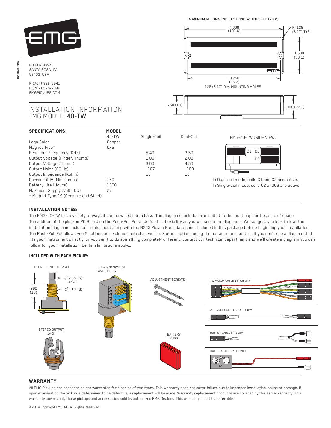
EMG 40-TW (dual-mode, 40 housing)
The 4-inch housing version of the TW, for 5-string and narrow 6-string basses.
String spread: 3.00" (76.2 mm) maximum string spread.
In the box: TW push-pull pot (25K) with plug-on circuit board, 25K tone pot, 15" TW pickup cable, 5.5" connect cables, 6" output cable, stereo output jack, battery buss, 7" battery cable, adjustment screws.
| Single coil | Dual coil | |
|---|---|---|
| Resonant frequency (kHz) | 5.40 | 2.50 |
| Output, finger (V) | 1.00 | 2.00 |
| Output, thump (V) | 3.00 | 4.50 |
| Noise at 60 Hz (dBV) | -107 | -109 |
| Output impedance (kΩ) | 10 | 10 |
Current: 160 µA at 9 V, about 1,500 hours per battery. Maximum supply 27 V.
Hookups on this sheet
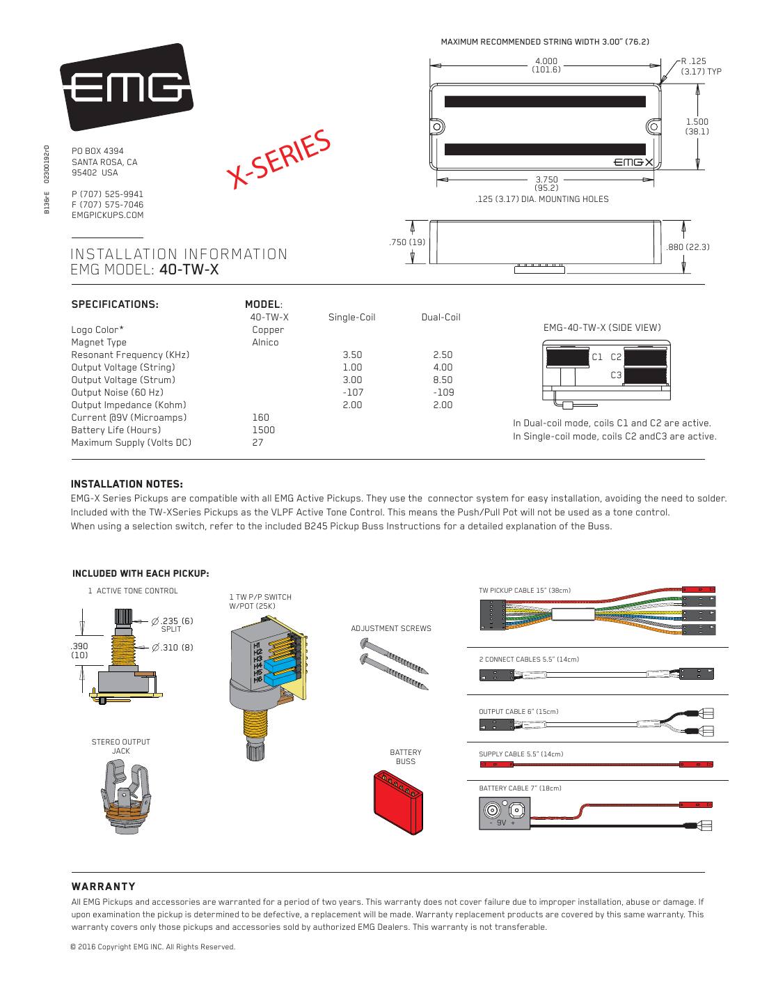
EMG 40-TW-X (dual-mode, X series)
The X version of the 40-TW: alnico magnets and 2K output impedance.
String spread: 3.00" (76.2 mm) maximum string spread.
In the box: TW push-pull pot (25K) with plug-on circuit board, 25K tone pot, 15" TW pickup cable, 5.5" connect cables, 6" output cable, stereo output jack, battery buss, 7" battery cable, adjustment screws. X versions add a 5.5" supply cable.
| Single coil | Dual coil | |
|---|---|---|
| Resonant frequency (kHz) | 3.50 | 2.50 |
| Output, finger (V) | 1.00 | 4.00 |
| Output, thump (V) | 3.00 | 8.50 |
| Noise at 60 Hz (dBV) | -107 | -109 |
| Output impedance (kΩ) | 2 | 2 |
Current: 160 µA at 9 V, about 1,500 hours per battery. Maximum supply 27 V.
Hookups on this sheet
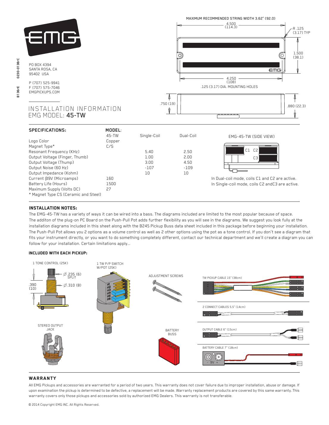
EMG 45-TW (dual-mode, 6-string)
The 6-string housing version of the TW.
String spread: 3.62" (92.0 mm) maximum string spread.
In the box: TW push-pull pot (25K) with plug-on circuit board, 25K tone pot, 15" TW pickup cable, 5.5" connect cables, 6" output cable, stereo output jack, battery buss, 7" battery cable, adjustment screws.
| Single coil | Dual coil | |
|---|---|---|
| Resonant frequency (kHz) | 5.40 | 2.50 |
| Output, finger (V) | 1.00 | 2.00 |
| Output, thump (V) | 3.00 | 4.50 |
| Noise at 60 Hz (dBV) | -107 | -109 |
| Output impedance (kΩ) | 10 | 10 |
Current: 160 µA at 9 V, about 1,500 hours per battery. Maximum supply 27 V.
Hookups on this sheet
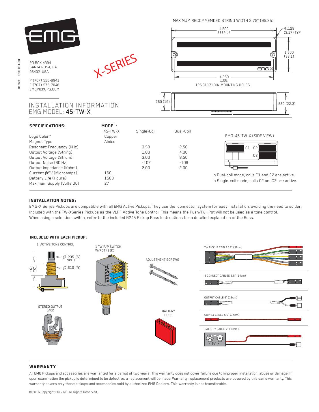
EMG 45-TW-X (dual-mode, X series, 6-string)
The X version of the 45-TW.
String spread: 3.75" (95.25 mm) maximum string spread.
In the box: TW push-pull pot (25K) with plug-on circuit board, 25K tone pot, 15" TW pickup cable, 5.5" connect cables, 6" output cable, stereo output jack, battery buss, 7" battery cable, adjustment screws. X versions add a 5.5" supply cable.
| Single coil | Dual coil | |
|---|---|---|
| Resonant frequency (kHz) | 3.50 | 2.50 |
| Output, finger (V) | 1.00 | 4.00 |
| Output, thump (V) | 3.00 | 8.50 |
| Noise at 60 Hz (dBV) | -107 | -109 |
| Output impedance (kΩ) | 2 | 2 |
Current: 160 µA at 9 V, about 1,500 hours per battery. Maximum supply 27 V.
Hookups on this sheet
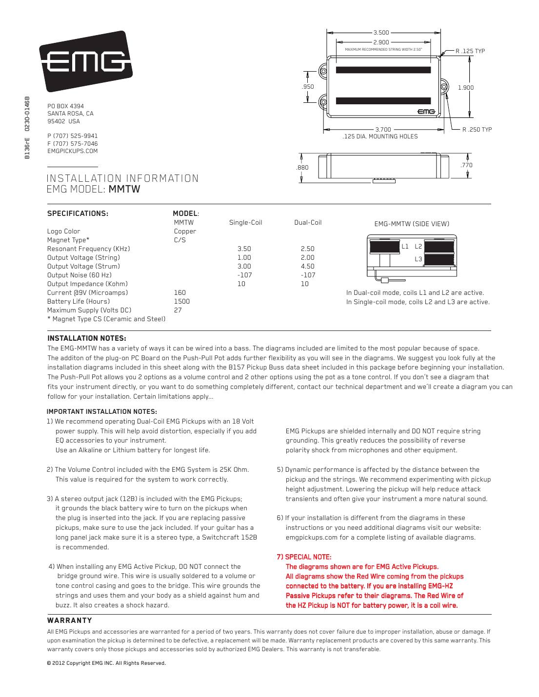
EMG MMTW (dual-mode Music Man 4-string)
A dual-mode TW pickup in the Music Man 4-string shape.
String spread: 2.50" maximum string spread.
In the box: TW push-pull pot (25K) with plug-on circuit board, 25K tone pot, 15" TW pickup cable, 5.5" connect cables, 6" output cable, stereo output jack, battery buss, 7" battery cable, adjustment screws.
| Single coil | Dual coil | |
|---|---|---|
| Resonant frequency (kHz) | 3.50 | 2.50 |
| Output, finger (V) | 1.00 | 2.00 |
| Output, thump (V) | 3.00 | 4.50 |
| Noise at 60 Hz (dBV) | -107 | -107 |
| Output impedance (kΩ) | 10 | 10 |
Current: 160 µA at 9 V, about 1,500 hours per battery. Maximum supply 27 V.
Hookups on this sheet
- EMG TW pickups: setting the push-pull coil switch
- EMG TW push-pull pot: four ways to use the 25K pot
- EMG TW: one or two TW pickups, complete hookups
- EMG: long panel jack, older EMGs, battery holders and 18 V
- EMG labels the MMTW coils L1, L2, L3: dual-coil uses L1 and L2; single-coil uses L2 and L3.
EMG MM5TW (dual-mode Music Man 5-string)
The 5-string Music Man shape TW.
String spread: 3.08" (78.2 mm) maximum string spread.
In the box: TW push-pull pot (25K) with plug-on circuit board, 25K tone pot, 15" TW pickup cable, 5.5" connect cables, 6" output cable, stereo output jack, battery buss, 7" battery cable, adjustment screws.
| Single coil | Dual coil | |
|---|---|---|
| Resonant frequency (kHz) | 3.50 | 2.50 |
| Output, finger (V) | 1.00 | 2.00 |
| Output, thump (V) | 3.00 | 4.50 |
| Noise at 60 Hz (dBV) | -107 | -107 |
| Output impedance (kΩ) | 10 | 10 |
Current: 160 µA at 9 V, about 1,500 hours per battery. Maximum supply 27 V.
Hookups on this sheet
- EMG TW pickups: setting the push-pull coil switch
- EMG TW push-pull pot: four ways to use the 25K pot
- EMG TW: one or two TW pickups, complete hookups
- EMG: long panel jack, older EMGs, battery holders and 18 V
- Coils: dual-coil uses L1 and L2; single-coil uses L2 and L3.
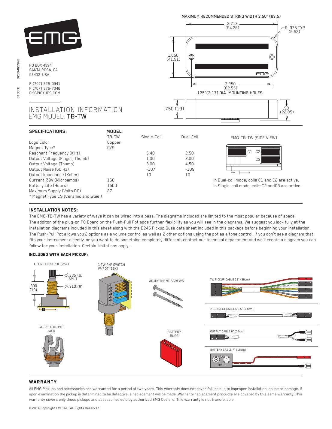
EMG TB-TW (dual-mode, TB housing)
The TW in EMG's TB housing.
String spread: 2.50" (63.5 mm) maximum string spread.
In the box: TW push-pull pot (25K) with plug-on circuit board, 25K tone pot, 15" TW pickup cable, 5.5" connect cables, 6" output cable, stereo output jack, battery buss, 7" battery cable, adjustment screws.
| Single coil | Dual coil | |
|---|---|---|
| Resonant frequency (kHz) | 5.40 | 2.50 |
| Output, finger (V) | 1.00 | 2.00 |
| Output, thump (V) | 3.00 | 4.50 |
| Noise at 60 Hz (dBV) | -107 | -109 |
| Output impedance (kΩ) | 10 | 10 |
Current: 160 µA at 9 V, about 1,500 hours per battery. Maximum supply 27 V.
Hookups on this sheet
Passive HZ pickups (5-wire cable)
EMG 35-HZ (passive, 35 housing)
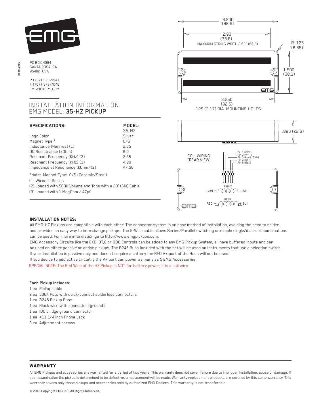
EMG's passive HZ pickups need no battery. They use a 5-wire quick-connect cable and solderless 250K/500K pots, so they still install without soldering in most basses.
String spread: 2.62" (66.5 mm) maximum string spread.
In the box: Pickup cable, two 500K solderless pots, B245 pickup buss, black ground wire with connector, IDC bridge-ground connector, #11 1/4" jack, 2 adjustment screws.
| 35-HZ | |
|---|---|
| Magnet | C/S |
| Inductance (H) | 2.65 |
| DC resistance (kΩ) | 8.0 |
| Resonant frequency, loaded (kHz) | 2.85 |
| Resonant frequency, 1 MΩ/47 pF (kHz) | 4.90 |
| Impedance at resonance (kΩ) | 47.5 |
Passive: no battery. Loaded resonance is measured with the pots and a 20 ft cable, as on EMG's sheet.
Hookups on this sheet
- Every HZ diagram on this sheet is written out on our EMG-HZ passive wiring page; we haven't repeated them here.
EMG 40-HZ (passive, 40 housing)
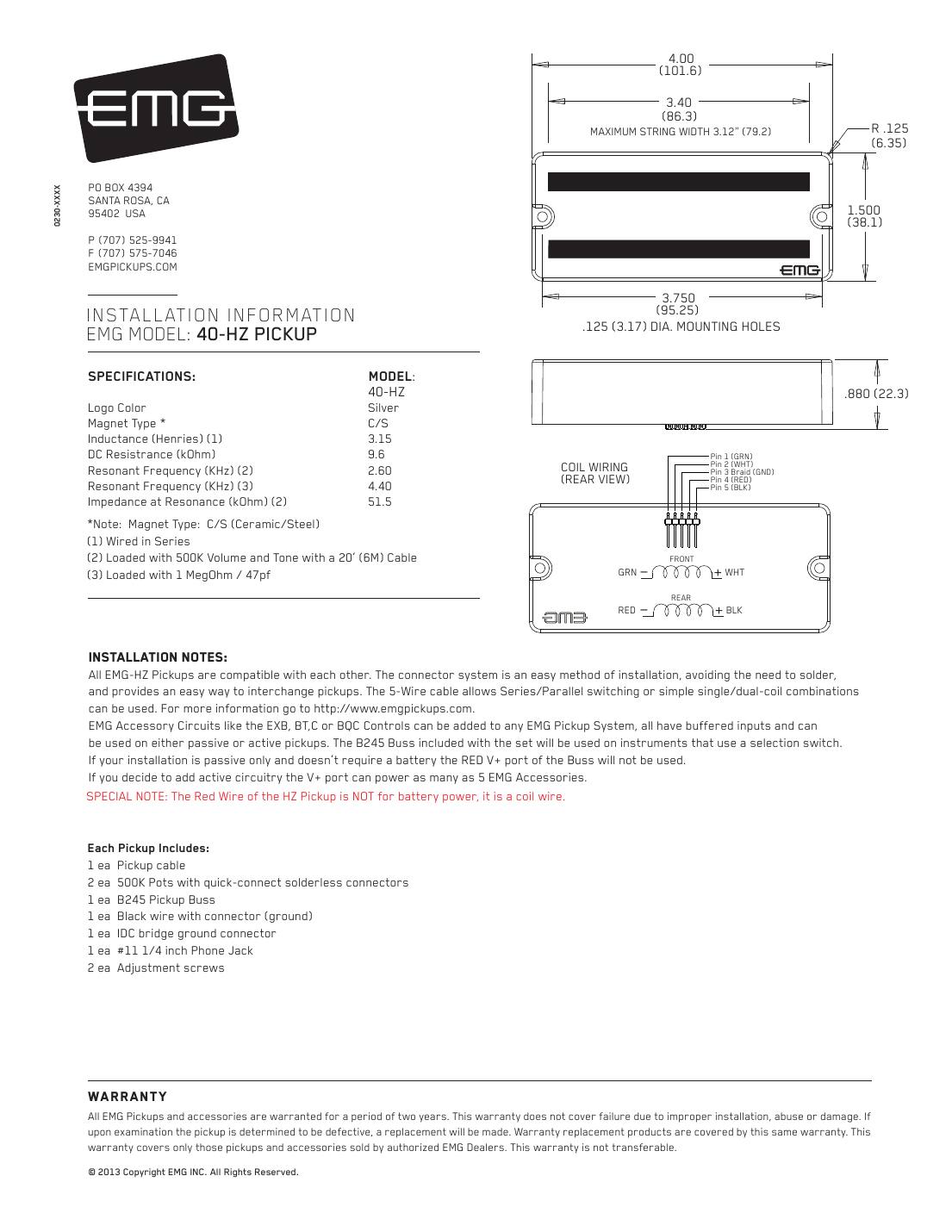
The passive HZ in the 4-inch housing for 5-string and narrow 6-string basses.
String spread: 3.12" (79.2 mm) maximum string spread.
In the box: Pickup cable, two 500K solderless pots, B245 pickup buss, black ground wire with connector, IDC bridge-ground connector, #11 1/4" jack, 2 adjustment screws.
| 40-HZ | |
|---|---|
| Magnet | C/S |
| Inductance (H) | 3.15 |
| DC resistance (kΩ) | 9.6 |
| Resonant frequency, loaded (kHz) | 2.60 |
| Resonant frequency, 1 MΩ/47 pF (kHz) | 4.40 |
| Impedance at resonance (kΩ) | 51.5 |
Passive: no battery. Loaded resonance is measured with the pots and a 20 ft cable, as on EMG's sheet.
Hookups on this sheet
- All the hookups are on our EMG-HZ passive wiring page.
EMG 45-HZ (passive, 6-string)
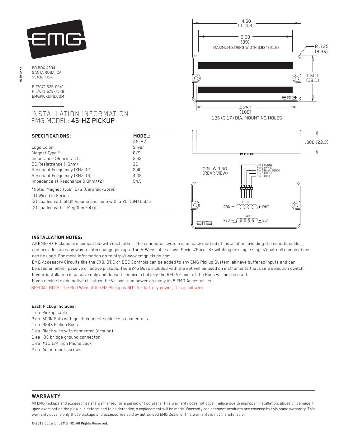
The passive HZ in the 6-string housing.
String spread: 3.62" (91.9 mm) maximum string spread.
In the box: Pickup cable, two 500K solderless pots, B245 pickup buss, black ground wire with connector, IDC bridge-ground connector, #11 1/4" jack, 2 adjustment screws.
| 45-HZ | |
|---|---|
| Magnet | C/S |
| Inductance (H) | 3.62 |
| DC resistance (kΩ) | 11 |
| Resonant frequency, loaded (kHz) | 2.40 |
| Resonant frequency, 1 MΩ/47 pF (kHz) | 4.05 |
| Impedance at resonance (kΩ) | 54.5 |
Passive: no battery. Loaded resonance is measured with the pots and a 20 ft cable, as on EMG's sheet.
Hookups on this sheet
- All the hookups are on our EMG-HZ passive wiring page.
EMG TB-HZ (passive, TB housing)
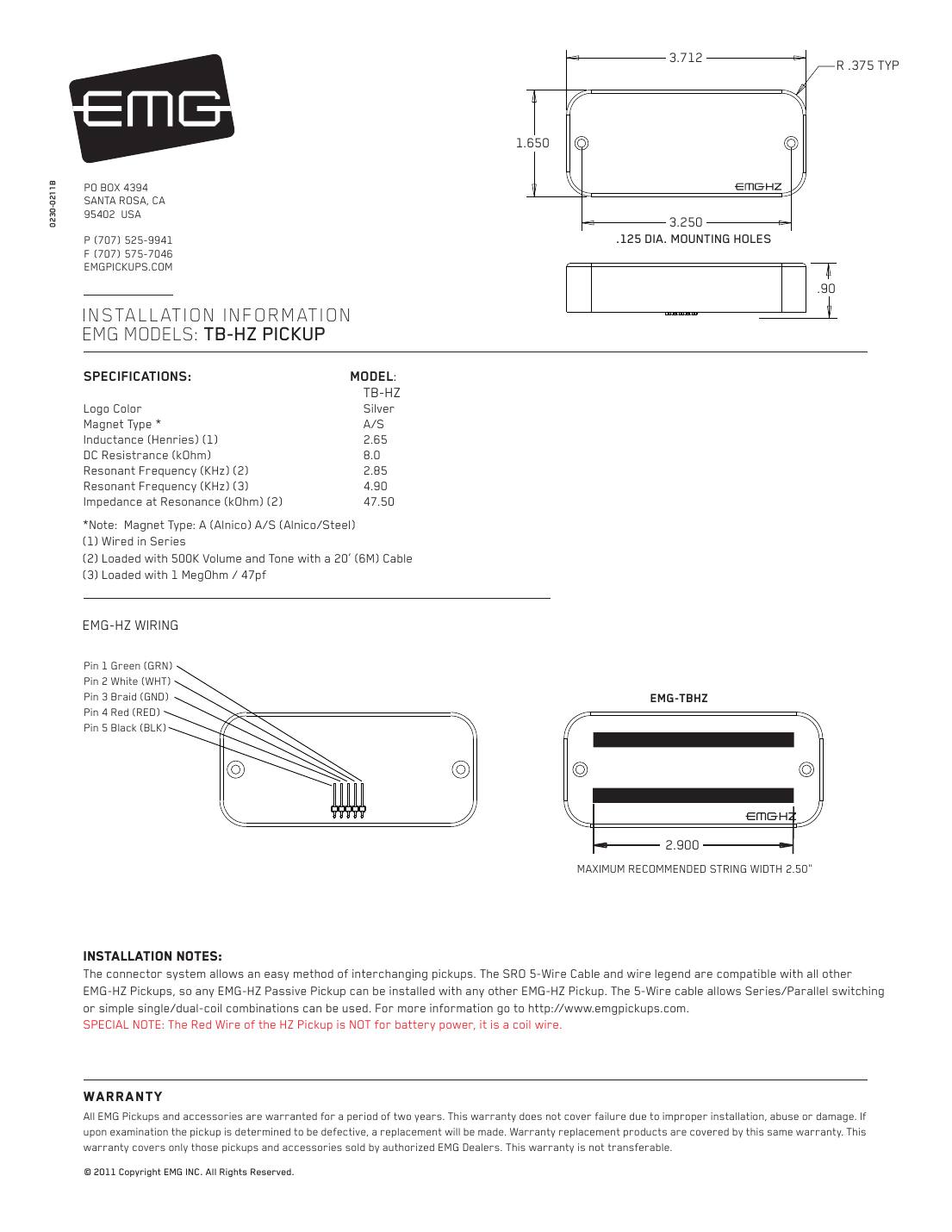
The passive HZ in EMG's TB housing, with alnico and steel magnets. Same 5-wire cable as every other HZ, so it mixes with any HZ pickup.
String spread: 2.50" maximum string spread.
In the box: 5-wire pickup cable and adjustment screws. The sheet's diagrams use 500K volume and tone pots and a 0.047 µF tone cap.
| TB-HZ | |
|---|---|
| Magnet | A/S |
| Inductance (H) | 2.65 |
| DC resistance (kΩ) | 8.0 |
| Resonant frequency, loaded (kHz) | 2.85 |
| Resonant frequency, 1 MΩ/47 pF (kHz) | 4.90 |
| Impedance at resonance (kΩ) | 47.5 |
Passive: no battery. Loaded resonance is measured with the pots and a 20 ft cable, as on EMG's sheet.
Hookups on this sheet
- Phase reverse (sheet diagram #3): send the red wire to ground with the shield and use green as the output. Black and white stay joined either way.
- The single- and two-pickup hookups match our EMG-HZ passive wiring page.
EMG MMHZ (passive Music Man shape, 4-string)
A passive HZ in the Music Man shape, bar-magnet construction, for 4-string basses only.
String spread: 2.75" recommended string spread.
In the box: 5-pin cable pre-wired for humbucking series, adjustment screws.
| MMHZ | |
|---|---|
| Magnet | Bar style |
| Inductance (H) | 2.65 |
| DC resistance (kΩ) | 8 |
| Resonant frequency, loaded (kHz) | 2.85 |
| Resonant frequency, 1 MΩ/47 pF (kHz) | 4.90 |
| Impedance at resonance (kΩ) | 47.5 |
Passive: no battery. Loaded resonance is measured with the pots and a 20 ft cable, as on EMG's sheet.
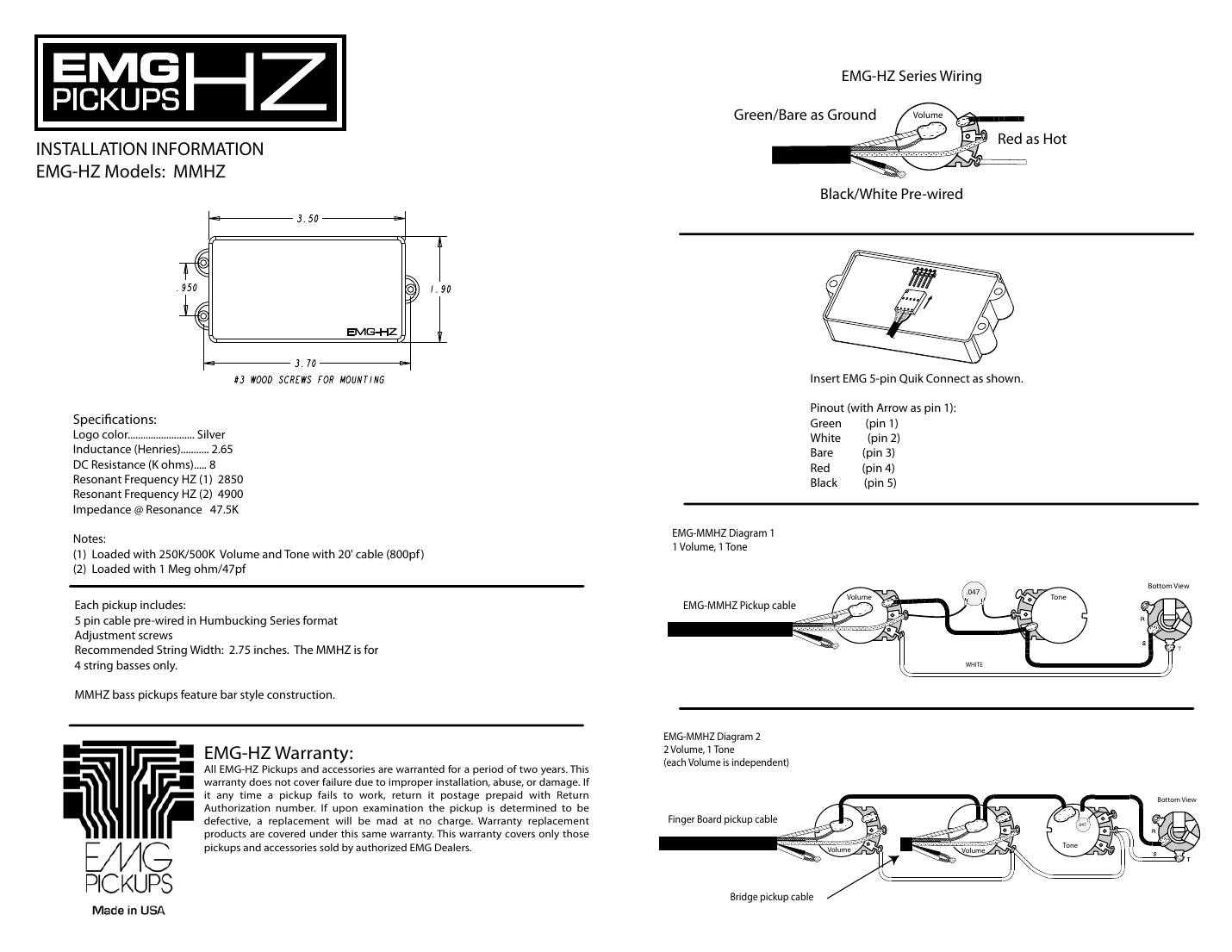
Hookups on this sheet
- The one-page sheet shows two hookups: 1 volume + 1 tone, and 2 volumes (independent) + 1 tone, both with a 0.047 µF tone cap. Ground is green and bare, hot is red, black and white are joined.
- Pinout with the arrow as pin 1: green 1, white 2, bare 3, red 4, black 5.
Passive GZR and J-HZ sets (2-wire cable)
EMG P-HZ, Geezer Butler GZR model (passive P)
Geezer Butler's passive split-P set: two identical halves with alnico 5 magnets and gold logos. The half with the EMG logo goes under the D and G strings so its cable reaches the control cavity.
String spread: 4-string P bass.
In the box: 250K volume and 250K tone (solderless), 12" P pickup cable, 5.5" connect cables, 6" output cable, mono output jack, bridge-ground connector and 6" bridge ground wire, 4 adjustment screws.
| P-HZ | |
|---|---|
| Magnet | Alnico 5 |
| Inductance (H) | 6.12 |
| DC resistance (kΩ) | 11.20 |
| Resonant frequency, loaded (kHz) | 1.77 |
| Resonant frequency, 1 MΩ/47 pF (kHz) | 2.36 |
| Impedance at resonance (kΩ) | 68.0 |
Passive: no battery. Loaded resonance is measured with the pots and a 20 ft cable, as on EMG's sheet.
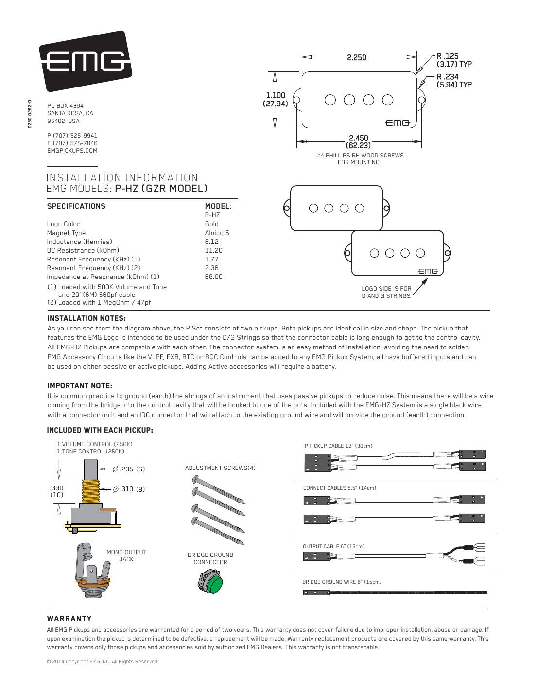
Hookups on this sheet
- The sheet shows a volume-only hookup (diagram #3) and the usual P-bass volume + tone (diagram #4).
EMG PJ-HZ set, Geezer Butler GZR model (passive PJ)
Geezer Butler's passive PJ set: the P-HZ at the neck and a long J-HZ at the bridge, both alnico 5, wired volume/volume/tone.
String spread: 4-string PJ bass.
In the box: Two 250K volumes and a 250K tone (solderless), 12" P cable, 10" J cable, 5.5" connect cables, 6" output cable, mono jack, bridge-ground connector and 6" ground wire, 8 adjustment screws.
| P-HZ | J-HZ (long) | |
|---|---|---|
| Magnet | Alnico 5 | Alnico 5 |
| Inductance (H) | 6.12 | 2.60 |
| DC resistance (kΩ) | 11.2 | 7.60 |
| Resonant frequency, loaded (kHz) | 1.77 | 2.4 |
| Resonant frequency, 1 MΩ/47 pF (kHz) | 2.36 | 3.2 |
| Impedance at resonance (kΩ) | 68.0 | 41.3 |
Passive: no battery. Loaded resonance is measured with the pots and a 20 ft cable, as on EMG's sheet.
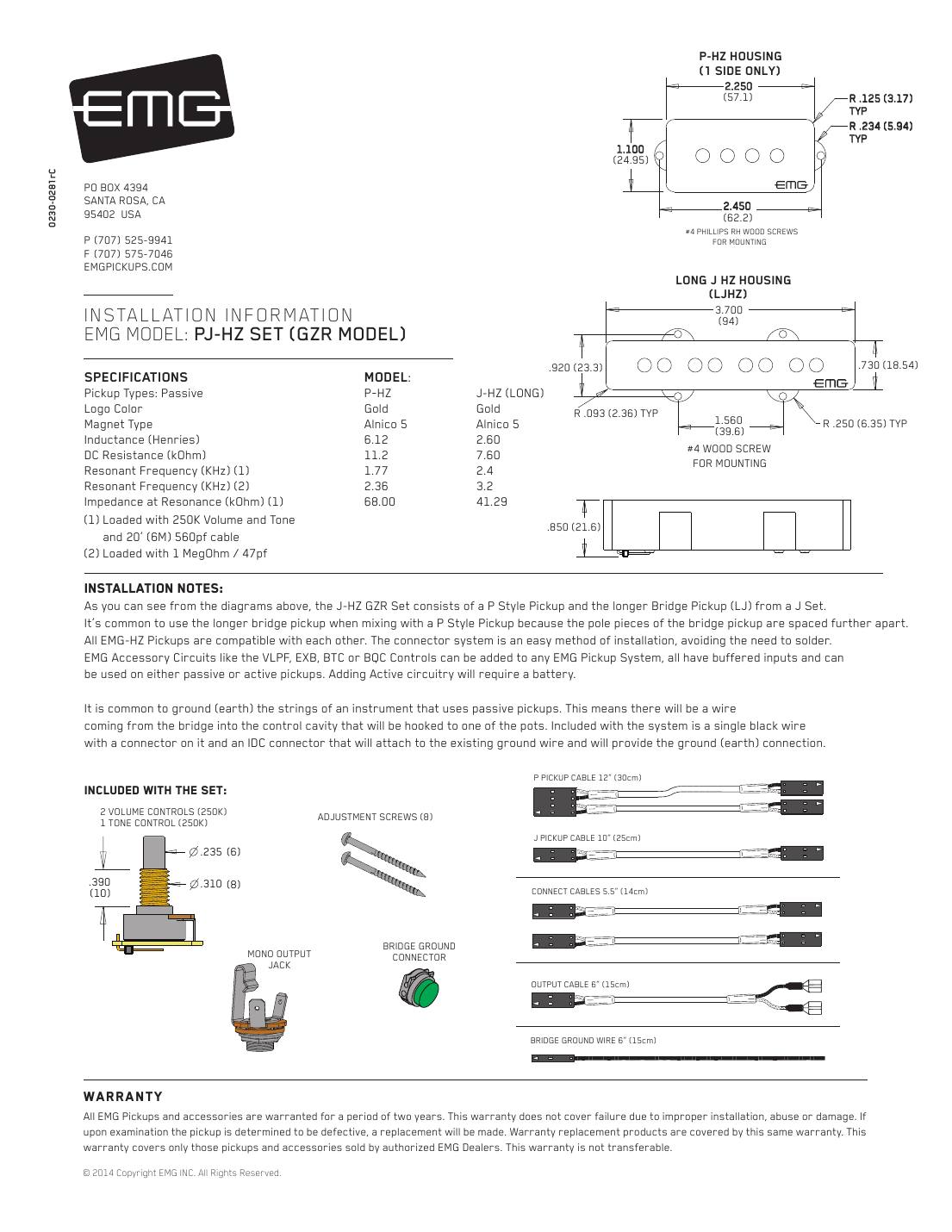
Hookups on this sheet
EMG J-HZ / JVHZ set, alnico 2 or alnico 5 (passive J)
Passive J pair: short (SJ) for the neck, long (LJ) for the bridge. Split-coil design (one coil for E/A, one for D/G) for hum reduction. 4-string only.
String spread: 4-string J bass.
In the box: Two 250K volumes and a 250K tone (solderless), 12" and 10" J cables, 5.5" connect cables, 6" output cable, mono jack, bridge-ground connector and 6" ground wire, 8 adjustment screws.
| JHZ short (A5) | JHZ long (A5) | JVHZ short (A2) | JVHZ long (A2) | |
|---|---|---|---|---|
| Magnet | Alnico 5 | Alnico 5 | Alnico 2 | Alnico 2 |
| Inductance (H) | 2.38 | 2.80 | 3.0 | 3.48 |
| DC resistance (kΩ) | 6.89 | 7.60 | 6.83 | 7.60 |
| Resonant frequency, loaded (kHz) | 3.5 | 3.5 | 3.0 | 3.0 |
| Resonant frequency, 1 MΩ/47 pF (kHz) | 4.0 | 4.0 | 3.4 | 3.4 |
| Impedance at resonance (kΩ) | 52.3 | 61.5 | 56.5 | 65.6 |
Passive: no battery. Loaded resonance is measured with the pots and a 20 ft cable, as on EMG's sheet.
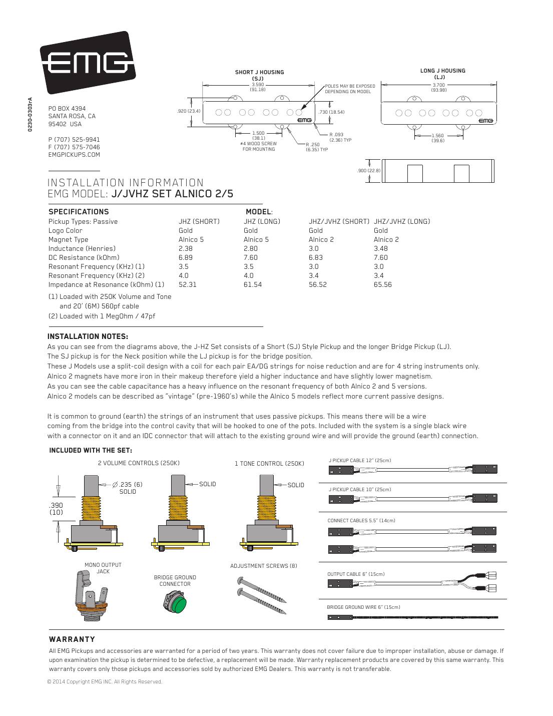
Hookups on this sheet
- The library calls this sheet 'JVHZ Set Alnico 2/5'; it covers both the alnico 5 J-HZ and the alnico 2 JVHZ.
EMG hookups, wire by wire
EMG active, one pickup: volume only, or volume and tone
The single-pickup hookup on every EMG active sheet (sheet diagrams #2 and #3). Everything plugs together; nothing is soldered unless you have a long panel jack.
You need: 1 EMG 25K volume, 1 EMG 25K tone (optional), pickup cable, connect cable, output cable, stereo output jack, battery buss, 9 V battery clip.
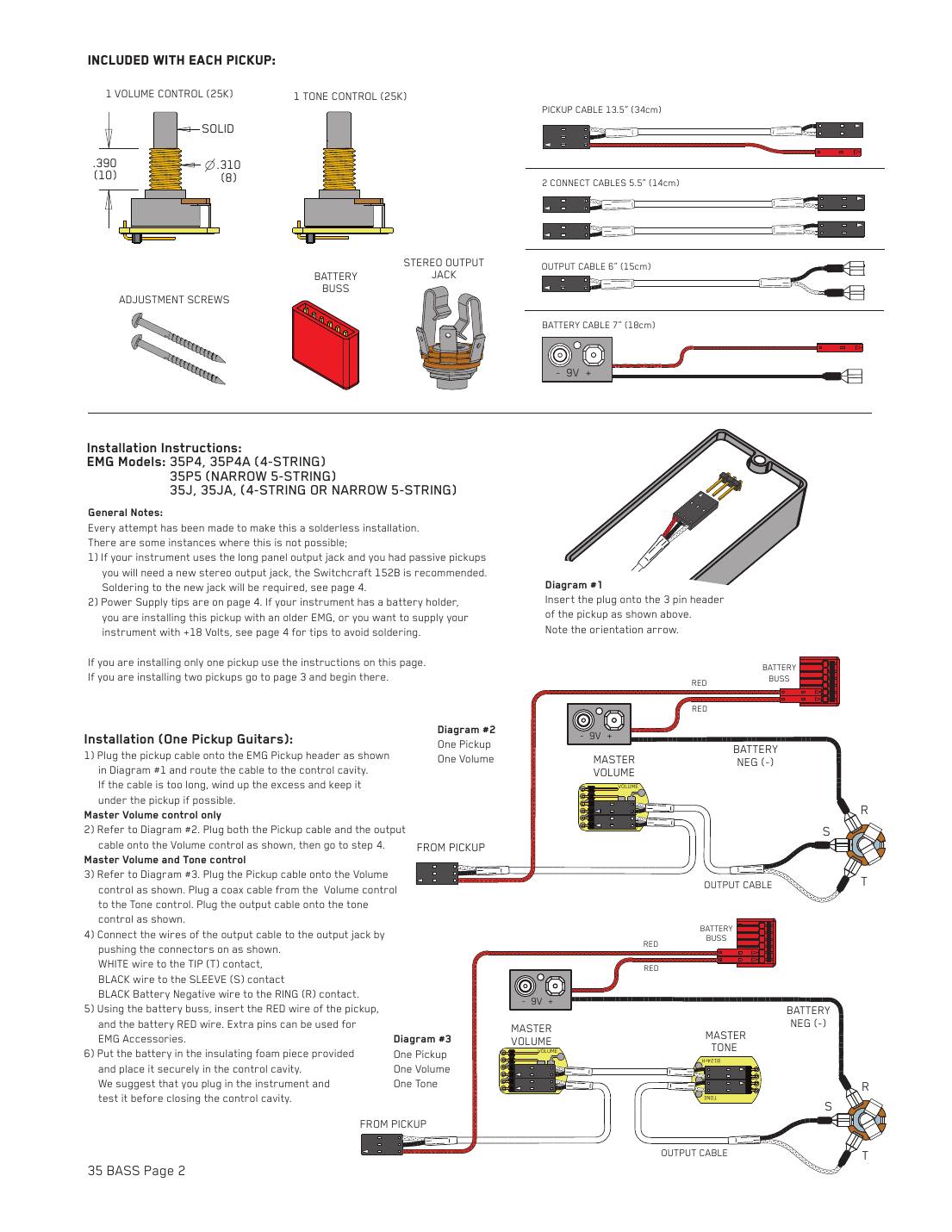
| # | From | To | Notes |
|---|---|---|---|
| 1 | Pickup cable | Pickup: 3-pin header | Line up the orientation arrow |
| 2 | Pickup cable, other end | Volume control | |
| 3 | Volume only: output cable | Volume control | Skip the tone rows |
| 4 | With tone: connect (coax) cable | Volume control to tone control | |
| 5 | With tone: output cable | Tone control | |
| 6 | Output cable: white | Output jack: tip (T) | Signal |
| 7 | Output cable: black | Output jack: sleeve (S) | Ground |
| 8 | Battery clip: black (negative) | Output jack: ring (R) | The stereo jack switches the battery on when a cable is plugged in |
| 9 | Pickup red wire and battery red wire | Battery buss (red) | Spare pins power EMG accessories |
Step by step
- Plug the pickup cable onto the pickup's 3-pin header (arrow lined up) and route it to the control cavity. Keep any extra cable under the pickup.
- Plug the pickup cable onto the volume. For volume only, plug the output cable onto the volume too. For volume and tone, run a connect cable from the volume to the tone and plug the output cable onto the tone.
- Push the output cable onto the jack: white to tip, black to sleeve. Push the battery clip's black wire onto the ring.
- Plug the pickup's red wire and the battery's red wire onto the battery buss.
- Put the battery in its foam sleeve, plug in and test before you close the cavity.
- Don't reconnect the bridge (string) ground: EMG active pickups don't need it.
- X-series pickups use the VLPF active tone here instead of the passive tone: see the X-series hookup below.
EMG active, two pickups: volume, volume, master tone (J-bass style)
The most common two-pickup hookup (sheet diagram #4 on most EMG active sheets). The controls are daisy-chained with connect cables; there's no selector switch.
You need: 2 EMG 25K volumes, 1 EMG 25K tone, 2 pickup cables, 2 connect cables, output cable, stereo jack, battery buss, 9 V battery clip.
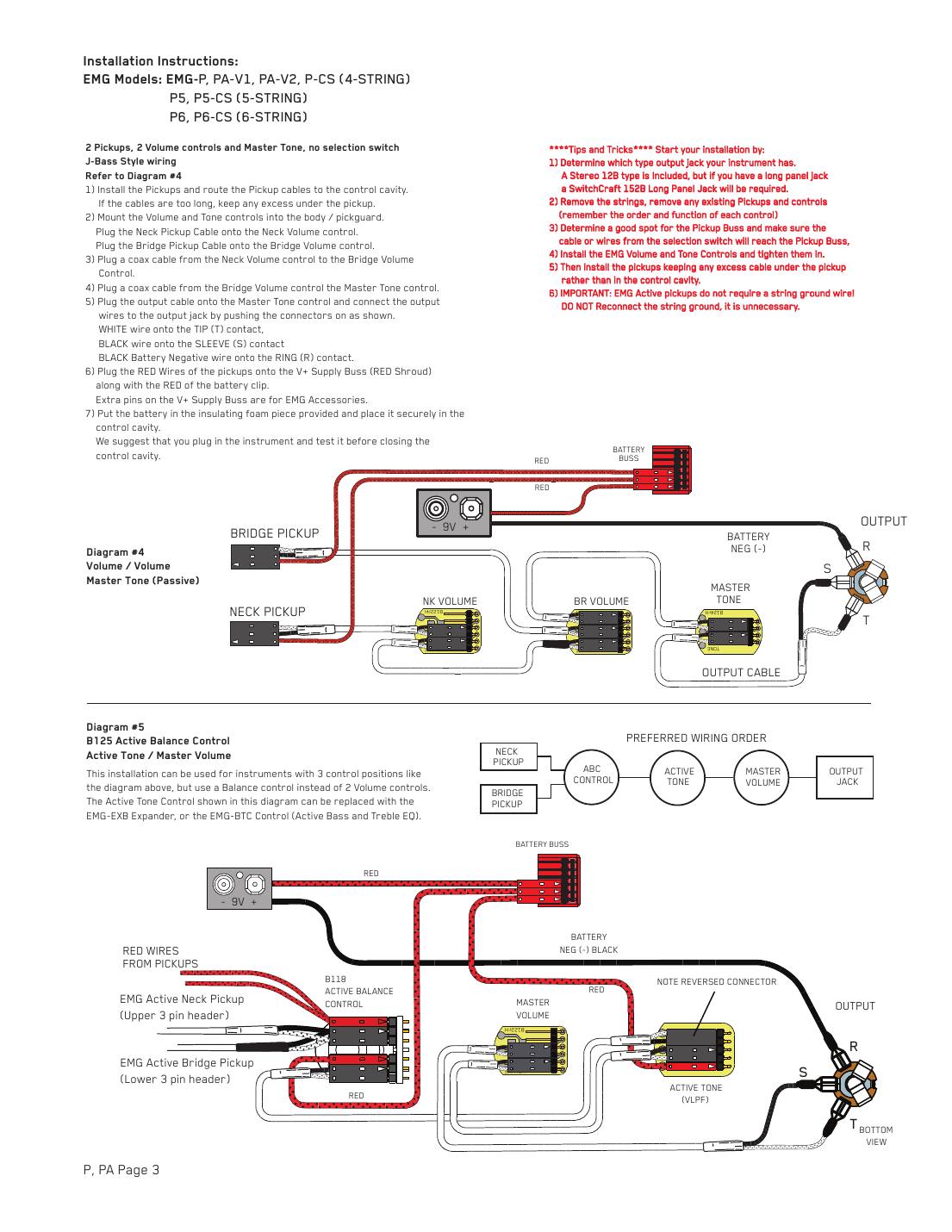
| # | From | To | Notes |
|---|---|---|---|
| 1 | Neck pickup cable | Neck volume | |
| 2 | Bridge pickup cable | Bridge volume | |
| 3 | Connect cable | Neck volume to bridge volume | |
| 4 | Connect cable | Bridge volume to master tone | |
| 5 | Output cable | Master tone | |
| 6 | Output cable: white | Output jack: tip (T) | Signal |
| 7 | Output cable: black | Output jack: sleeve (S) | Ground |
| 8 | Battery clip: black (negative) | Output jack: ring (R) | The stereo jack switches the battery on when a cable is plugged in |
| 9 | Both pickups' red wires and the battery red | Battery buss (red shroud) |
Step by step
- Fit the pickups and route their cables to the control cavity, keeping extra cable under the pickups.
- Mount the controls. Plug the neck pickup onto the neck volume and the bridge pickup onto the bridge volume.
- Connect cable from the neck volume to the bridge volume, and another from the bridge volume to the master tone.
- Output cable from the master tone to the jack: white to tip, black to sleeve, battery black to ring.
- Both pickups' red wires and the battery red onto the battery buss. Battery in its foam, then test.
- Any EMG active control that takes the 5-pin in/out connector (EXB, BTC, BTS, BQC, VLPF) can replace the passive master tone.
EMG active, two pickups with a 3-way switch (B245 pickup buss)
For basses with a pickup selector, EMG's B245 buss keeps the job solderless. Pickups plug into the buss, the switch wires screw into its green terminal block, and the buss output feeds the controls.
You need: B245 pickup buss, 25K master volume and master tone (or a volume for each pickup), connect cables, output cable, stereo jack, battery clip.
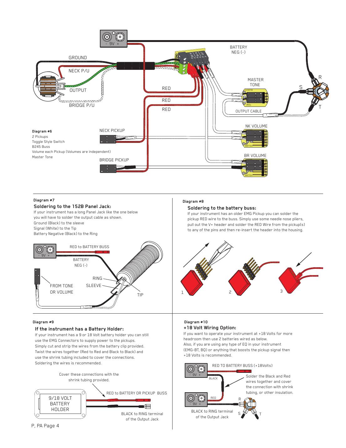
| # | From | To | Notes |
|---|---|---|---|
| 1 | Bridge pickup cable | B245 black shroud: position 1 (BR IN) | |
| 2 | Neck pickup cable | B245 black shroud: position 2 (NK IN) | |
| 3 | Switch wire from the bridge pickup lug | Green terminal block: BR | Strip and screw in |
| 4 | Switch wire from the neck pickup lug | Green terminal block: NK | |
| 5 | Switch output wire | Green terminal block: O | |
| 6 | Switch ground wire (if any) | Black GND terminal | |
| 7 | Connect cable | B245 position 3 (OUT) to master volume | |
| 8 | Connect cable | Master volume to master tone | |
| 9 | Output cable | Master tone | |
| 10 | Output cable: white | Output jack: tip (T) | Signal |
| 11 | Output cable: black | Output jack: sleeve (S) | Ground |
| 12 | Battery clip: black (negative) | Output jack: ring (R) | The stereo jack switches the battery on when a cable is plugged in |
| 13 | Pickup red wires and battery red | Red shroud (V+) |
Step by step
- Plug the bridge pickup into position 1 and the neck pickup into position 2 of the B245's black shroud.
- Strip the selector switch wires and screw them into the green terminal block: bridge to BR, neck to NK, switch output to O, any switch ground to a black terminal.
- Connect cable from buss position 3 to the master volume, then from the master volume to the master tone.
- Output cable from the master tone to the jack: white to tip, black to sleeve, battery black to ring.
- Pickup and battery red wires onto the red V+ shroud. Battery in, then test every switch position.
- Independent volumes (sheet diagram #6 on the P, TB, MM, LJ and J5 sheets): plug each pickup into its own volume, run each volume into its B245 input, and take the buss output to the master tone.
- If you don't have a B245, EMG sells it separately: you'd otherwise have to solder at the switch.
EMG active, two pickups: active balance, active tone, master volume
For basses with three control positions: a balance (pan) control replaces the two volumes. EMG's drawings use the B125 or B118 active balance control.
You need: EMG B125 or B118 active balance control, 25K master volume, EMG active tone (VLPF, EXB or BTC), connect cables, output cable, stereo jack, battery clip.
| # | From | To | Notes |
|---|---|---|---|
| 1 | Neck pickup cable | Balance control: upper 3-pin header | |
| 2 | Bridge pickup cable | Balance control: lower 3-pin header | |
| 3 | Connect cable | Balance output to master volume | As drawn |
| 4 | Connect cable | Master volume to active tone | Reversed connector on the active tone end |
| 5 | Output cable | Active tone | |
| 6 | Output cable: white | Output jack: tip (T) | Signal |
| 7 | Output cable: black | Output jack: sleeve (S) | Ground |
| 8 | Battery clip: black (negative) | Output jack: ring (R) | The stereo jack switches the battery on when a cable is plugged in |
| 9 | Pickup reds, balance and active tone red wires, battery red | Battery buss | Active controls need power too |
Step by step
- Plug the neck pickup onto the balance control's upper 3-pin header and the bridge pickup onto the lower one.
- Connect cable from the balance control to the master volume.
- Connect cable from the master volume to the active tone; note EMG's reversed connector at the active tone.
- Output cable from the active tone to the jack: white to tip, black to sleeve, battery black to ring.
- Every red wire (pickups, active controls, battery) onto the battery buss. Test before closing up.
- EMG's 'preferred wiring order' box lists balance, then active tone, then master volume, then jack, but the drawing chains the master volume before the active tone. Both orders work; we've followed the drawing.
- The active tone can be swapped for an EXB expander or BTC (bass and treble).
EMG X series: volume with the VLPF active tone
X-series pickups ship with the VLPF active tone instead of a passive tone pot. The hookups are the same as the standard ones except for how the VLPF connects and gets power.
You need: 25K volume(s), VLPF active tone, connect cables, output cable, supply cable, stereo jack, battery buss, 9 V clip.
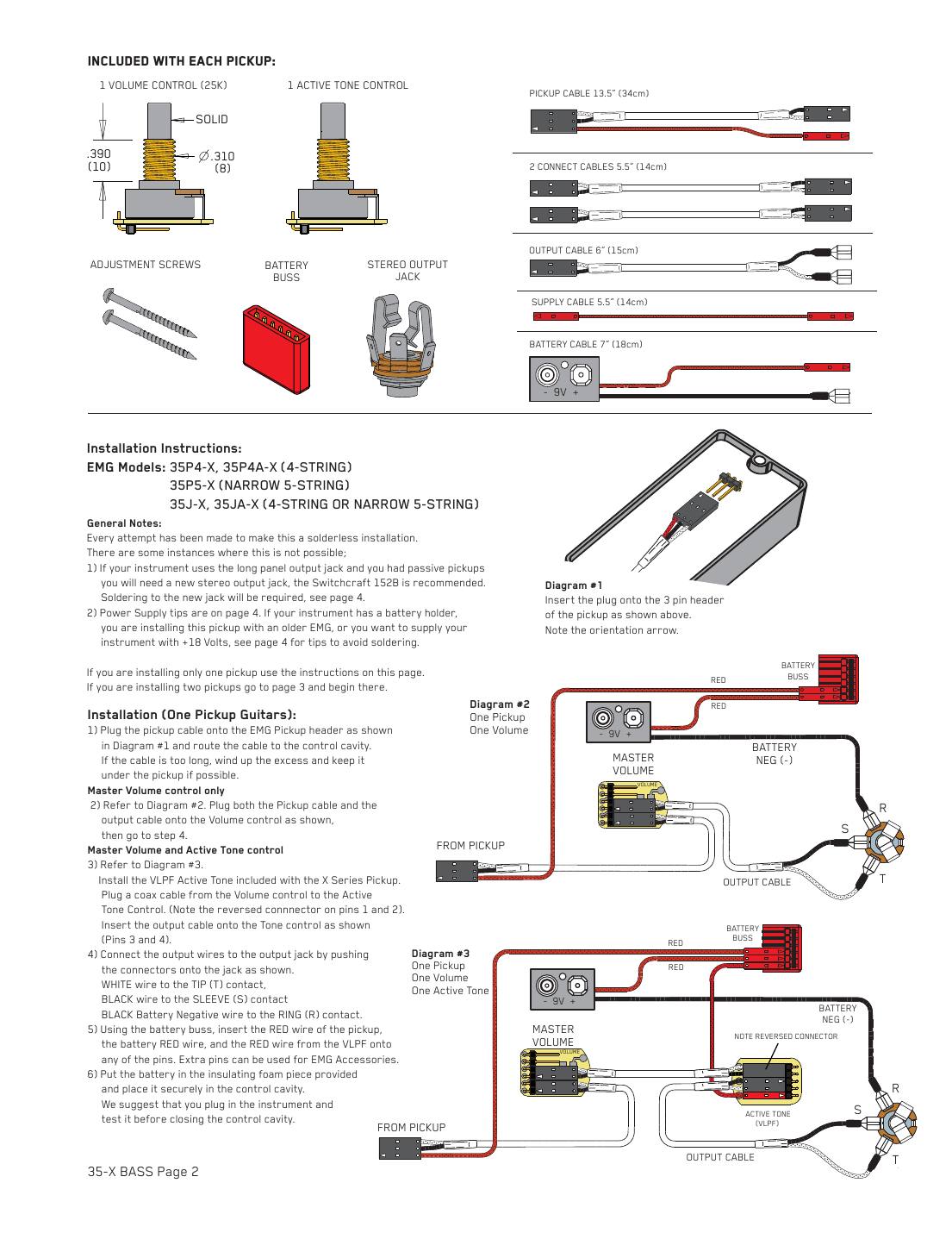
| # | From | To | Notes |
|---|---|---|---|
| 1 | Pickup cable | Volume control | Two pickups: neck to neck volume, bridge to bridge volume |
| 2 | Two pickups only: connect cable | Neck volume to bridge volume | |
| 3 | Connect cable | Volume (or bridge volume) to VLPF | Reversed connector on pins 1 and 2 |
| 4 | Output cable | VLPF: pins 3 and 4 | |
| 5 | Output cable: white | Output jack: tip (T) | Signal |
| 6 | Output cable: black | Output jack: sleeve (S) | Ground |
| 7 | Battery clip: black (negative) | Output jack: ring (R) | The stereo jack switches the battery on when a cable is plugged in |
| 8 | Pickup red wires, battery red, VLPF red (supply cable) | Battery buss |
Step by step
- Plug each pickup onto its volume control (for two pickups, link neck volume to bridge volume with a connect cable).
- Run a connect cable from the last volume to the VLPF; EMG reverses the connector on pins 1 and 2 at this end.
- Plug the output cable onto the VLPF's pins 3 and 4 and push it onto the jack: white to tip, black to sleeve, battery black to ring.
- Pickup, VLPF and battery red wires onto the battery buss. Battery in, then test.
- With a selector switch or balance control, the B245 and balance hookups above apply; put the VLPF where those show the tone.
EMG TW pickups: setting the push-pull coil switch
TW pickups have three coils. The push-pull pot's switch chooses dual-coil (humbucking) or single-coil, and the way you plug the TW cable onto the switch's single-row 6-pin header decides which position is which.
You need: TW pickup cable, TW push-pull pot with its plug-on circuit board.
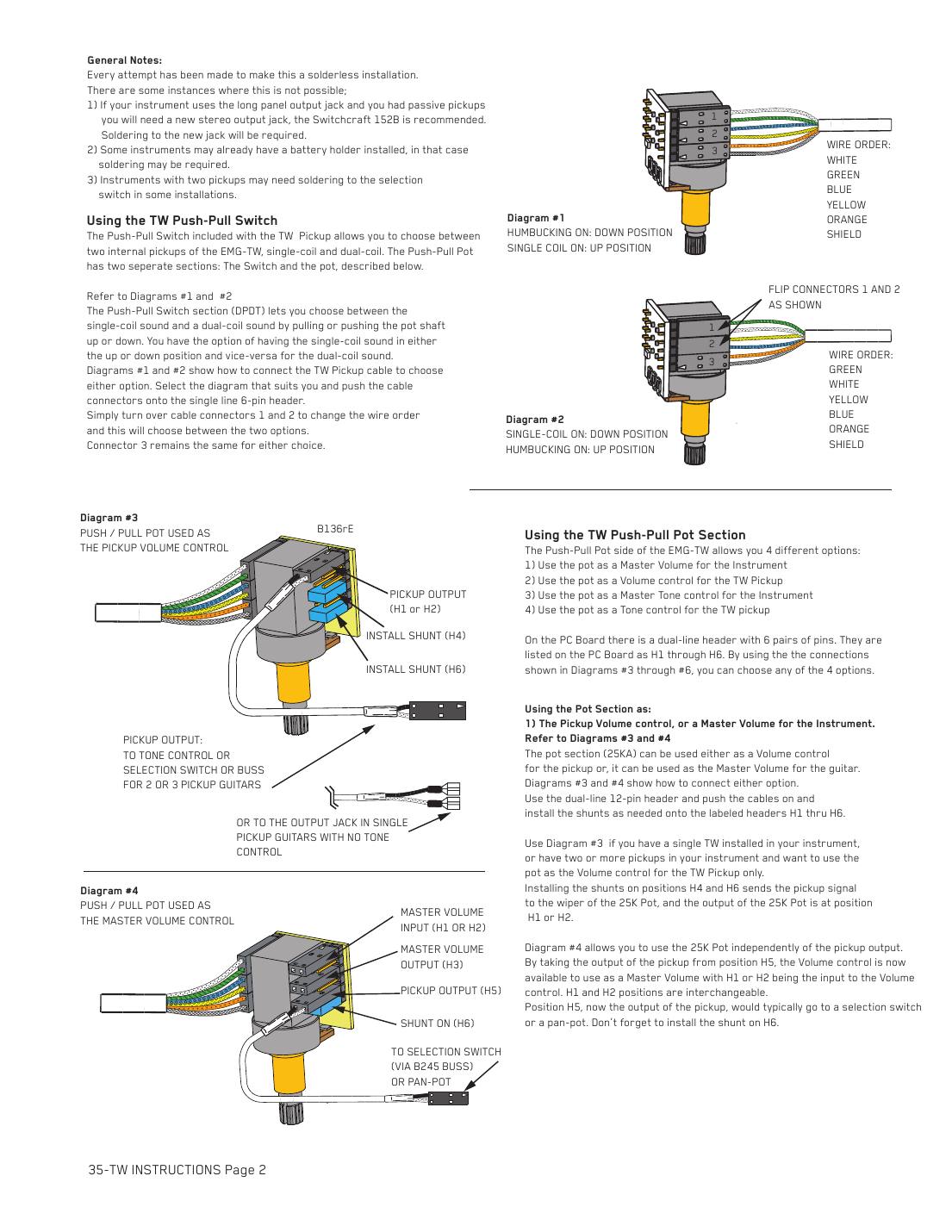
| # | From | To | Notes |
|---|---|---|---|
| 1 | TW cable connectors 1 and 2, as supplied | Switch: 6-pin header | Wire order white, green, blue, yellow, orange, shield: humbucking down, single coil up |
| 2 | TW cable connectors 1 and 2, flipped over | Switch: 6-pin header | Wire order green, white, yellow, blue, orange, shield: single coil down, humbucking up |
| 3 | TW cable connector 3 | Switch: 6-pin header | Same either way |
Step by step
- Decide whether you want the humbucking sound with the knob pushed down or pulled up.
- Humbucking down: plug connectors 1 and 2 on so the wire order reads white, green, blue, yellow, orange, shield (sheet diagram #1).
- Humbucking up: turn connectors 1 and 2 over so it reads green, white, yellow, blue, orange, shield (sheet diagram #2). Connector 3 doesn't change.
- Then set up the pot section (next hookup).
- Dual-coil mode uses coils C1 and C2; single-coil uses C2 and C3 (L1 to L3 on the MM TW sheets).
EMG TW push-pull pot: four ways to use the 25K pot
The pot half of the TW push-pull can be the TW's own volume, a master volume, the TW's own tone, or a master tone. You choose with shunts on the circuit board's dual-row header, positions H1 to H6.
You need: TW push-pull pot with circuit board, shunts, connect cables.
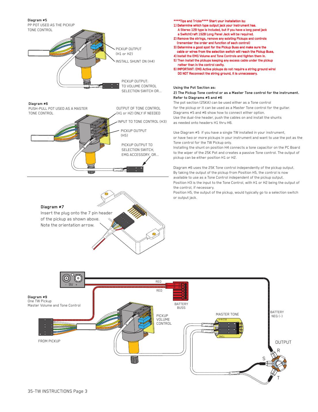
| # | From | To | Notes |
|---|---|---|---|
| 1 | Pickup volume: shunts | H4 and H6 | Pickup signal goes to the pot's wiper; output at H1 or H2 (sheet diagram #3) |
| 2 | Pickup volume: output | H1 or H2 | To the tone, a selector or buss, or the jack |
| 3 | Master volume: pickup output | H5 (shunt on H6) | Pickup output to a selector or pan pot (diagram #4) |
| 4 | Master volume: in and out | In at H1 or H2, out at H3 | H1 and H2 are interchangeable |
| 5 | Pickup tone: shunt | H4 | Connects the board's tone cap to the wiper; output at H1 or H2 (diagram #5) |
| 6 | Master tone: pickup output | H5 | To a selector, accessory or the jack (diagram #6) |
| 7 | Master tone: in and out | In at H3, out at H1 or H2 if needed |
Step by step
- Single TW, pot as its volume: shunts on H4 and H6, take the output from H1 or H2.
- Pot as a master volume: take the TW's output from H5 (shunt on H6) to your selector or pan pot; bring the selected signal back into H1 or H2 and out of H3.
- Pot as the TW's tone: shunt on H4, output from H1 or H2.
- Pot as a master tone: TW output from H5; tone input at H3, tone output at H1 or H2 if you need it.
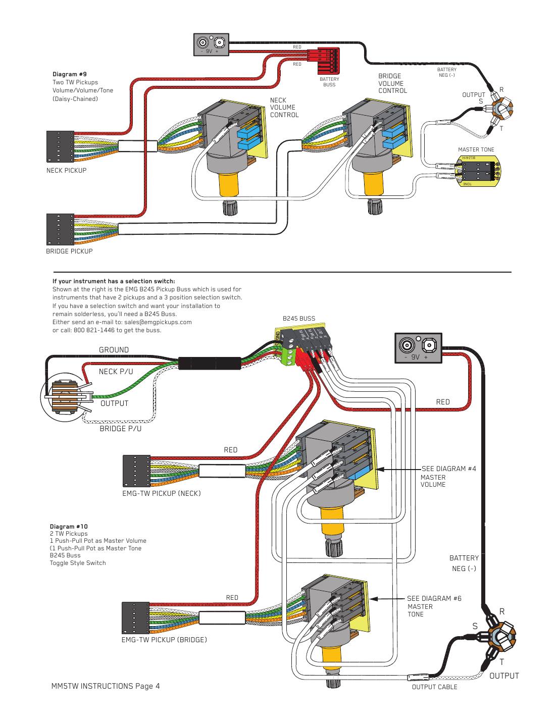
- Two TWs with a 3-way switch (sheet diagram #10): one push-pull is set up as the master volume and the other as the master tone, each TW's output (H5) goes to the B245, and the switch wires go into the buss terminal block.
EMG TW: one or two TW pickups, complete hookups
The complete TW hookups on EMG's sheets (diagrams #9 and #10).
You need: TW pickup(s) with push-pull pots, 25K tone, connect cables, output cable, stereo jack, battery buss, 9 V clip (B245 buss for a switch).
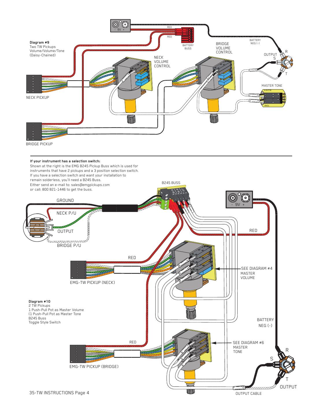
| # | From | To | Notes |
|---|---|---|---|
| 1 | One TW: TW cable | TW push-pull (as pickup volume) | Shunts H4 and H6 |
| 2 | One TW: connect cable | Push-pull output (H1/H2) to master tone | |
| 3 | Two TWs: neck TW | Neck push-pull volume | Daisy-chained volume, volume, tone |
| 4 | Two TWs: connect cables | Neck volume to bridge volume to master tone | |
| 5 | Output cable | Master tone | |
| 6 | Output cable: white | Output jack: tip (T) | Signal |
| 7 | Output cable: black | Output jack: sleeve (S) | Ground |
| 8 | Battery clip: black (negative) | Output jack: ring (R) | The stereo jack switches the battery on when a cable is plugged in |
| 9 | Every TW red wire and the battery red | Battery buss |
Step by step
- Set each TW's coil switch (wire order) as above.
- One TW: use its push-pull as the pickup volume, then a connect cable to the master tone.
- Two TWs, no switch: neck push-pull to bridge push-pull to master tone, with connect cables.
- Output cable to the jack: white to tip, black to sleeve, battery black to ring. All red wires onto the battery buss, then test both coil modes.
- Each TW draws 160 µA, so battery life is about half that of a standard EMG (about 1,500 hours).
EMG J system: plugging into the pre-wired control board
The J and J-X systems come with the volume, volume and tone already on one circuit board. Mount it on the control plate, then plug everything into it.
You need: J or J-X system (pickups, control board, output cable, stereo jack, battery clip).
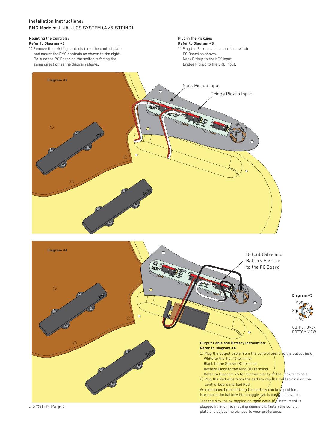
| # | From | To | Notes |
|---|---|---|---|
| 1 | Neck pickup cable | Control board: NEK input | |
| 2 | Bridge pickup cable | Control board: BRG input | |
| 3 | Output cable from the control board | Jack: white to tip, black to sleeve | |
| 4 | Battery clip: black | Jack: ring (R) | |
| 5 | Battery clip: red | Control board terminal marked RED |
Step by step
- Remove the strings, cut the old pickup wires at the switch and the jack wires, and cut the bridge ground wire; it isn't reconnected.
- Check the short (neck) pickup fits the pickguard cutout; enlarge it if needed. Plug the cables onto the pickups and mount them, routing each cable through the hole followed by its red wire.
- Mount the control board on the plate with the circuit board facing the way EMG's drawing shows.
- Plug the neck pickup into NEK and the bridge pickup into BRG.
- Output cable to the jack (white tip, black sleeve), battery black to the ring, battery red to the board's RED terminal. Test, then fit the plate and set pickup height.
- Check the battery fits before you start: EMG says the cavity may need enlarging, and a separate battery box on the back of the bass is always a good option.
EMG: long panel jack, older EMGs, battery holders and 18 V
The soldering and power options on page 4 of EMG's active sheets.
You need: Switchcraft 152B stereo long panel jack (if needed), solder, shrink tubing, second 9 V battery for 18 V.
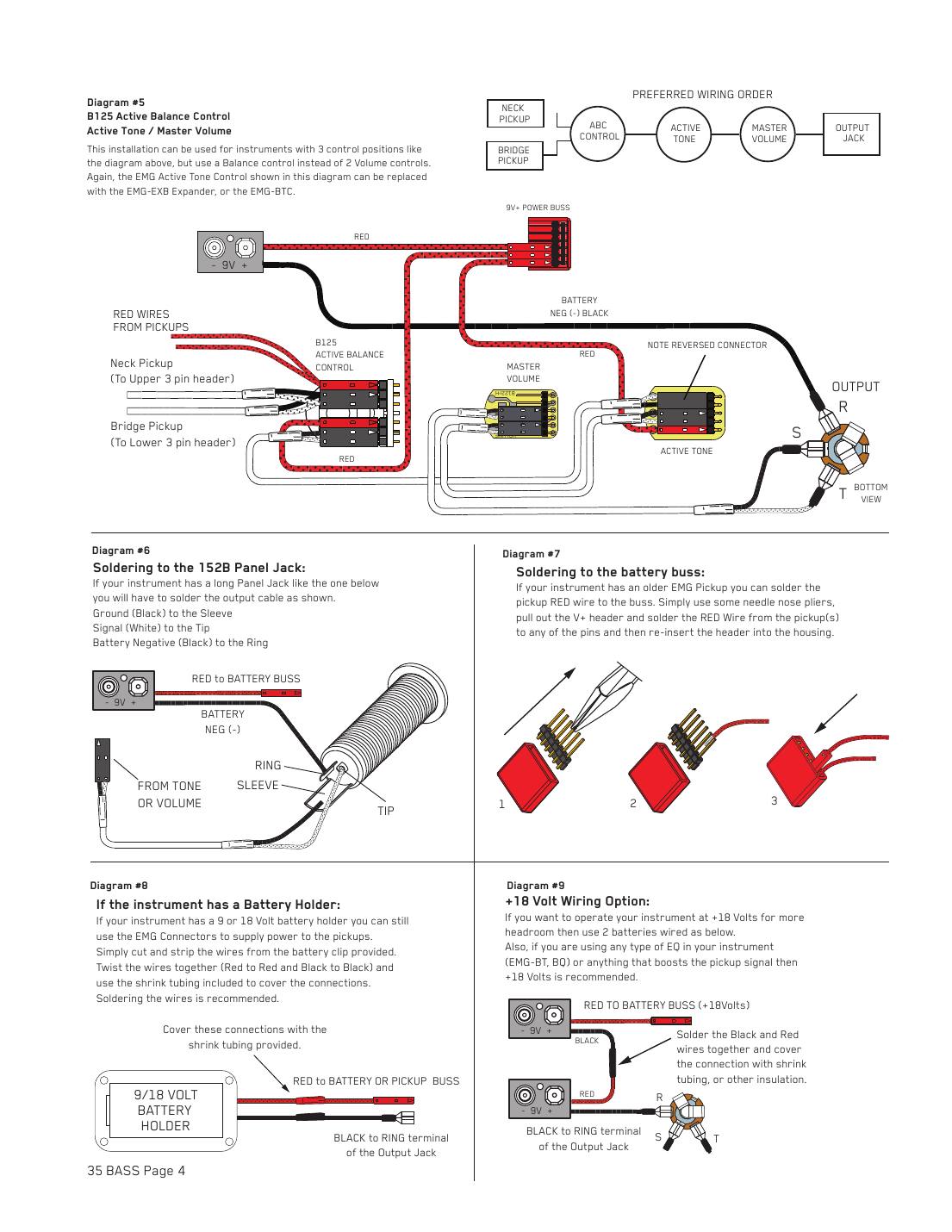
| # | From | To | Notes |
|---|---|---|---|
| 1 | Long panel jack: output cable black | 152B sleeve | Solder |
| 2 | Long panel jack: output cable white | 152B tip | Solder |
| 3 | Long panel jack: battery black | 152B ring | Solder |
| 4 | Older EMG pickup: red wire | Any pin of the battery buss's V+ header | Pull the header out, solder, push it back |
| 5 | Existing battery holder: red | Battery clip red (twisted, soldered, shrink-tubed) | Then to the battery buss |
| 6 | Existing battery holder: black | Battery clip black | Then to the jack ring |
| 7 | 18 V: battery 1 black | Battery 2 red | Solder and insulate |
| 8 | 18 V: free red | Battery buss | +18 V |
| 9 | 18 V: free black | Jack ring |
Step by step
- Long panel jack: a passive bass's mono long jack won't switch the battery. Fit a Switchcraft 152B and solder black to sleeve, white to tip, battery black to ring.
- Older EMG with a bare red wire: pull the V+ header out of the battery buss with needle-nose pliers, solder the red wire to any pin and push the header back in.
- Existing 9 V or 18 V battery holder: cut and strip the supplied battery clip, twist red to red and black to black, solder and cover with the shrink tubing. Red to the buss, black to the jack ring.
- 18 V: join the black of one battery to the red of the other. The free red goes to the battery buss and the free black to the jack ring.
- EMG recommends 18 V for more headroom, and whenever you add an EQ or anything else that boosts the pickup signal (EMG BT, BQ). Maximum supply for every EMG active pickup here is 27 V.
- The HZ sheets solder to a 151 long panel jack instead: passive pickups need no ring connection.
EMG-HZ passive pickups: the 5-wire cable and solderless pots
All of EMG's passive HZ pickups (35-HZ, 40-HZ, 45-HZ, TB-HZ, MMHZ) share the same 5-wire cable, so any HZ can be swapped for any other. The full set of HZ hookups (one pickup, two pickups, toggle and lever switches) is written out on our EMG-HZ page; here are the parts that differ from the active pickups.
You need: HZ pickup cable, solderless 250K/500K pots, B245 buss (for a switch), black ground wire with connector, IDC connector, mono jack.
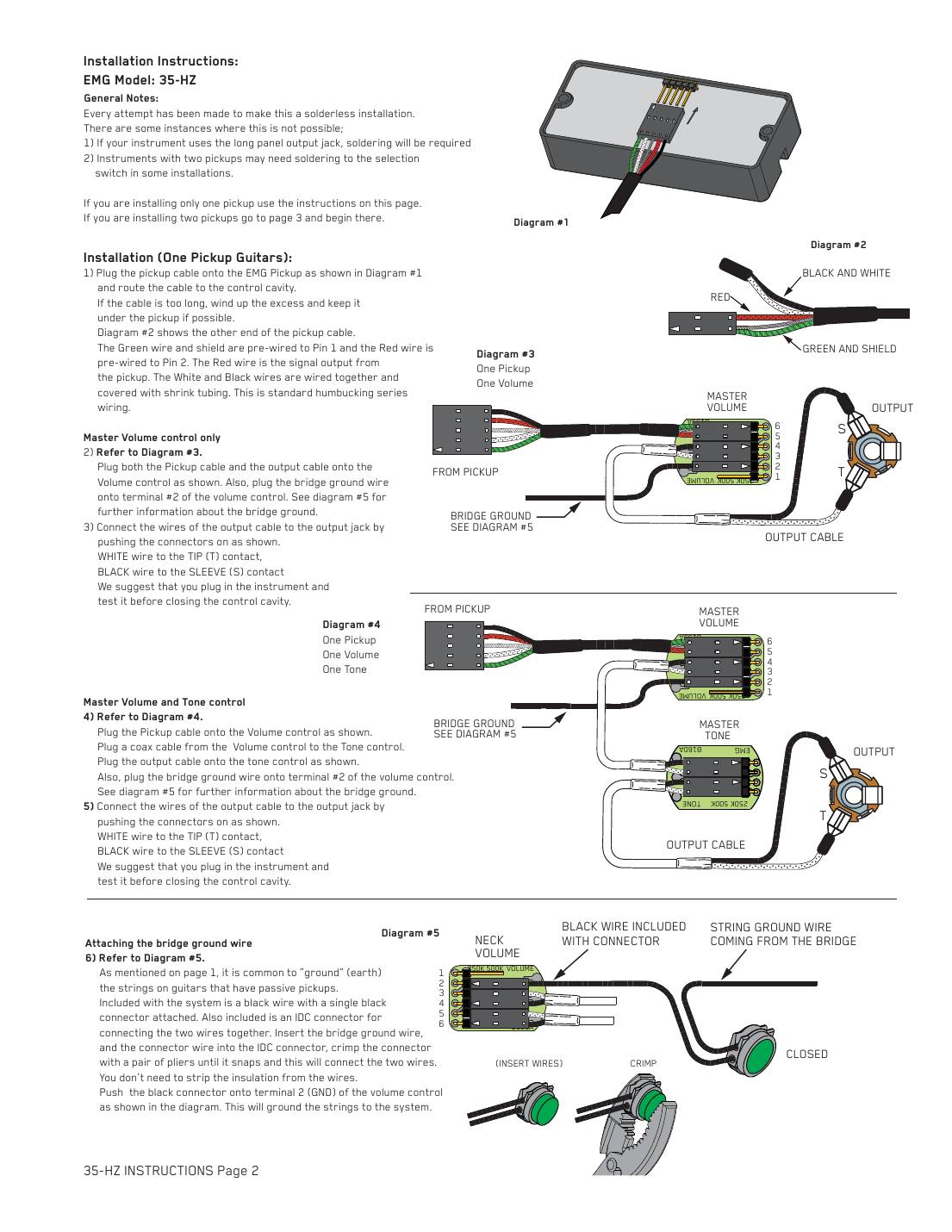
| # | From | To | Notes |
|---|---|---|---|
| 1 | Pickup cable: green and shield | Ground | Pre-wired to pin 1 of the pot connector |
| 2 | Pickup cable: red | Hot (signal) | Pre-wired to pin 2. Not a battery wire |
| 3 | Pickup cable: black and white | Joined and covered | Series (humbucking) |
| 4 | Bridge ground wire | IDC connector with EMG's black wire | Crimp with pliers; no stripping |
| 5 | EMG black ground wire | Volume control: terminal 2 (GND) | |
| 6 | Output cable: white | Jack tip | Mono jack |
| 7 | Output cable: black | Jack sleeve |
Step by step
- Plug the cable onto the pickup (pinout from the arrow: green 1, white 2, bare 3, red 4, black 5) and route it to the control cavity.
- Plug it onto the volume (and run a connect cable to the tone if you have one).
- Crimp the bridge ground wire and EMG's black wire together in the IDC connector and push the black connector onto volume terminal 2.
- Output cable to the jack: white to tip, black to sleeve. No battery.
- For two pickups and a switch, use the B245's black shroud and green terminal block as with the active pickups; the red V+ shroud stays empty.
- Unlike the active pickups, passive HZ pickups should have the strings grounded.
- For every HZ hookup wire by wire, see our EMG-HZ passive wiring page.
EMG GZR P-HZ, PJ-HZ and J-HZ/JVHZ sets: 2-wire passive hookups
Geezer Butler's GZR sets and the J-HZ/JVHZ set use a 2-pin cable (white and black) and solderless 250K pots. EMG's sheets show volume only, volume and tone, and the usual volume, volume, tone.
You need: Pickup cables, solderless 250K volume(s) and tone, connect cables, output cable, mono jack, bridge ground wire with IDC connector.
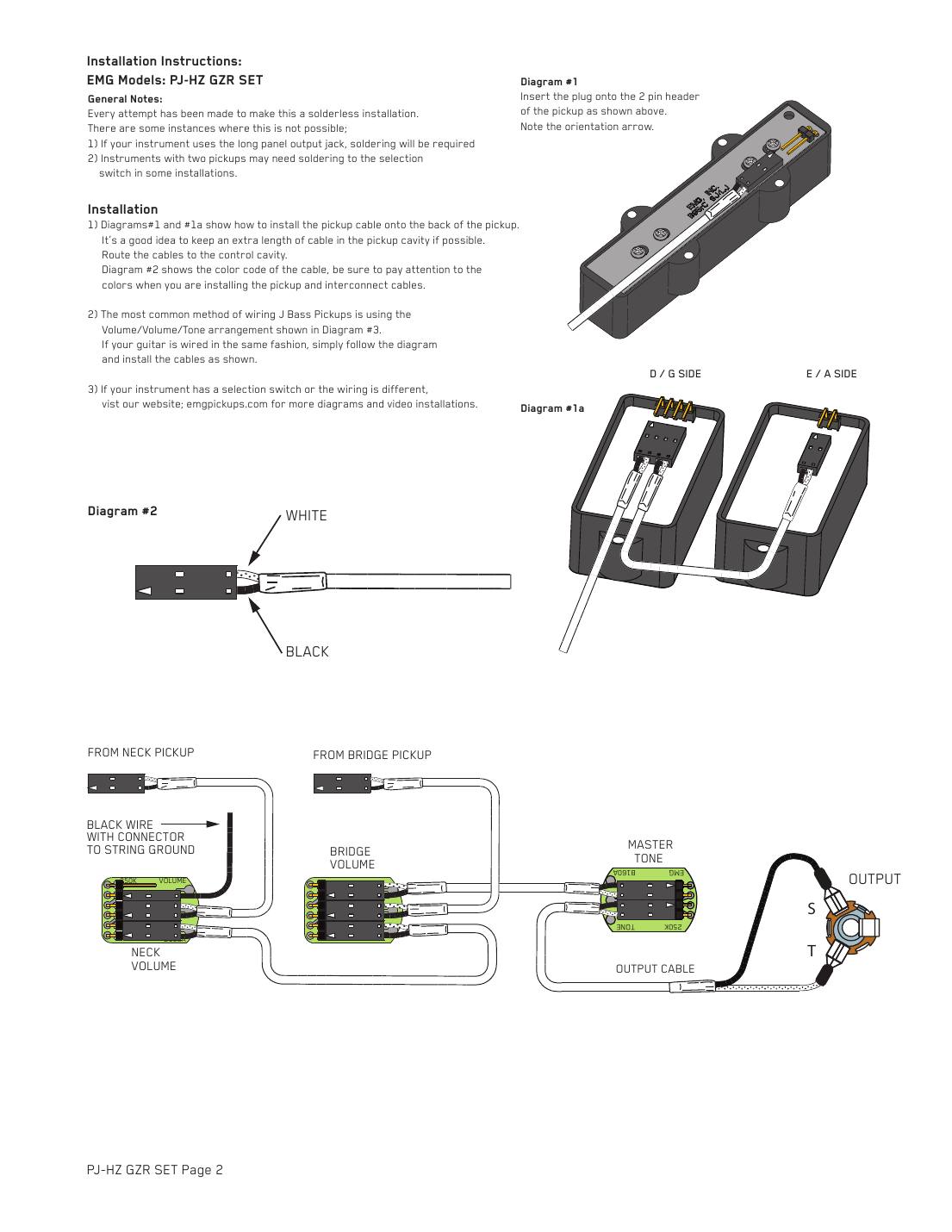
| # | From | To | Notes |
|---|---|---|---|
| 1 | Pickup cable | Pickup: 2-pin header | Line up the orientation arrow |
| 2 | Split P: D/G-side half | Its cable runs to the control cavity | The half with the EMG logo |
| 3 | Neck pickup cable | Neck volume | One pickup: the only volume |
| 4 | Bridge pickup cable | Bridge volume | |
| 5 | Connect cable | Neck volume to bridge volume | As drawn |
| 6 | Connect cable | Bridge volume to master tone | |
| 7 | Output cable | Master tone to the jack: tip (T) and sleeve (S) | Mono jack |
| 8 | Bridge ground wire | IDC connector, then to the volume's ground terminal |
Step by step
- Plug the cables onto the pickups (2-pin header, arrow lined up). On the split P, the EMG-logo half goes under the D and G strings so its cable reaches the cavity.
- Plug the neck pickup onto the neck volume and the bridge pickup onto the bridge volume, then link neck volume, bridge volume and master tone with connect cables.
- Output cable from the master tone to the mono jack.
- Crimp the bridge ground wire to EMG's black wire with the IDC connector and plug it onto the volume's ground terminal. Test before closing up.
- P-HZ alone: pickup into the volume, then the tone (or straight out for volume only), then the jack.
- EMG's sheets don't show selector-switch hookups for these sets and point you to emgpickups.com; the B245 buss works with all HZ pickups.
FAQ
Do EMG active pickups need the bridge (string) ground?
No. EMG says not to reconnect the string ground on active pickups; it isn't needed. Passive EMG-HZ pickups are different: ground the strings with the supplied black wire and IDC connector.
Why does EMG use 25K pots?
EMG active pickups have a low output impedance (10K, or 2K on X-series), so they use 25K volume and tone pots, which come in the box. Passive HZ pickups use 250K or 500K pots like any passive pickup.
Why do EMG pickups need a stereo output jack?
The battery's negative wire goes to the jack's ring. Plugging in a mono cable connects ring to sleeve and turns the battery on; unplugging turns it off. A mono long panel jack has to be swapped for a stereo one such as the Switchcraft 152B.
Should I run my EMGs at 9 V or 18 V?
9 V works. EMG recommends 18 V (two batteries) for more headroom, for the high-output MMCS and MM5CS, and whenever you add an EQ such as the BTC or BQC. Every active pickup here handles up to 27 V.
What's the difference between EMG and EMG-X pickups?
X-series pickups have more headroom (2K output impedance, up to 8.5 V on a hard thump) and come with the VLPF active tone instead of a passive tone pot. The VLPF needs its own red supply wire on the battery buss.
Is the red wire on an EMG-HZ pickup for the battery?
No. On the passive HZ pickups the red wire is a coil wire (it's the hot output in the standard series wiring). Only active EMGs have a red battery wire.
Related
- EMG bass pickups
- EMG-HZ passive bass pickup wiring
- EMG J, JA and J-CS wiring
- EMG PJHZ wiring kit
- All bass wiring diagrams
- DiMarzio bass wiring diagrams
Questions about a hookup? Call 877-839-3531 or email sales@bestbassgear.com.