Bartolini Bass Wiring Diagrams
Bartolini bass wiring diagrams, written out as text: all 15 Bartolini sheets in our library, covering 1-, 4- and 6-conductor pickups and their switching, the 8TC and 9E active pickups, the NTMB-918 and NTBT-918 preamps, the MPB2-918 piezo buffer, active/passive switching, the blend pot, stereo jacks and fitting Bartolini pickups to Music Man electronics. Find your pickup or preamp for the controls and where each lead goes, then follow the hookup. Each has Bartolini's original drawing and a PDF download.
Before you start
- Passive Bartolini pickups use 250K pots. The NTMB and NTBT preamps use a 25K volume, 50K EQ pots and a dual 250K blend.
- On 4-conductor Bartolini pickups, black is hot for series wiring, red and white are joined and insulated, and green and bare go to ground.
- Anything with a battery (8TC, 9E, NTMB, NTBT, TC3, MPB2) needs a stereo output jack: the battery's black goes to the ring, so plugging in turns it on. Unplug when you're done.
- Don't overheat the side of a Bartolini blend pot when you solder ground wires to it.
- Where a drawing is a small scan or a switch layout, this page says which wire goes to which control and tells you to follow the drawing for the lugs. Those spots are marked.
Find your pickup or preamp
Passive pickups and cable
- 1-conductor (coax) pickups: volume, volume, tone or blend
- 4-conductor pickups: series, parallel and switching
- 6-conductor quad-coil pickups: P forward / 4-coil humbucker / P reverse
Active pickups
- 8TC active P-Bass pickup
- 9E active Jazz Bass pickups (J pair and P-J)
- 9E Jazz Bass with the NTMB 3-band preamp
Controls and jacks
- Bartolini blend pot wiring (25K and 250K)
- Stereo jack connections
- Bartolini MM, MV or DL pickups to Music Man electronics
Preamps
- Active/passive switch on NTBT and NTMB preamps
- NTMB-918 3-band preamp (9 V or 18 V)
- NTBT-918 2-band preamp (9 V or 18 V)
- MPB2-918 piezo buffer (with an NTMB)
- Active/passive switch for TCT, NTCT and XTCT preamps
- Volume, volume, tone with the Bartolini TC3 (BBG diagram)
The hookups
- Passive, two pickups: volume, volume, master tone
- Two pickups into a Bartolini blend pot (pre-wired harness)
- Bartolini 4-conductor colour code: series, parallel and single coil
- NTMB-918 and NTBT-918 preamps: the harness, colour by colour
- Active/passive switch on Bartolini preamps (push/pull or DPDT toggle)
Bartolini diagrams by pickup and preamp
Passive pickups and cable
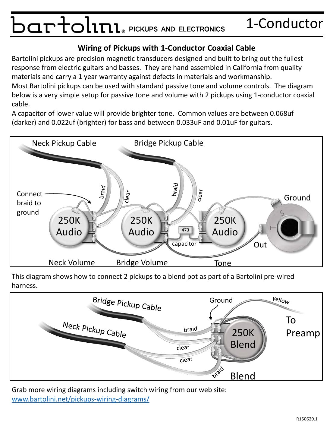
1-conductor (coax) pickups: volume, volume, tone or blend
For Bartolini pickups with single-conductor shielded cable: the clear centre is hot, the braid is ground. Bartolini shows two ways: passive volume, volume, tone, and into the blend pot of a pre-wired harness.
Controls: 250K audio volumes ×2, 250K audio tone, .047 µF cap, mono jack (or a Bartolini harness with a 250K blend).
| # | Wire | Goes to |
|---|---|---|
| 1 | Clear (centre) | Hot: volume middle lug (as Bartolini draws it), or a blend pot input |
| 2 | Braid | Ground: pot casing |
Wire it with
4-conductor pickups: series, parallel and switching
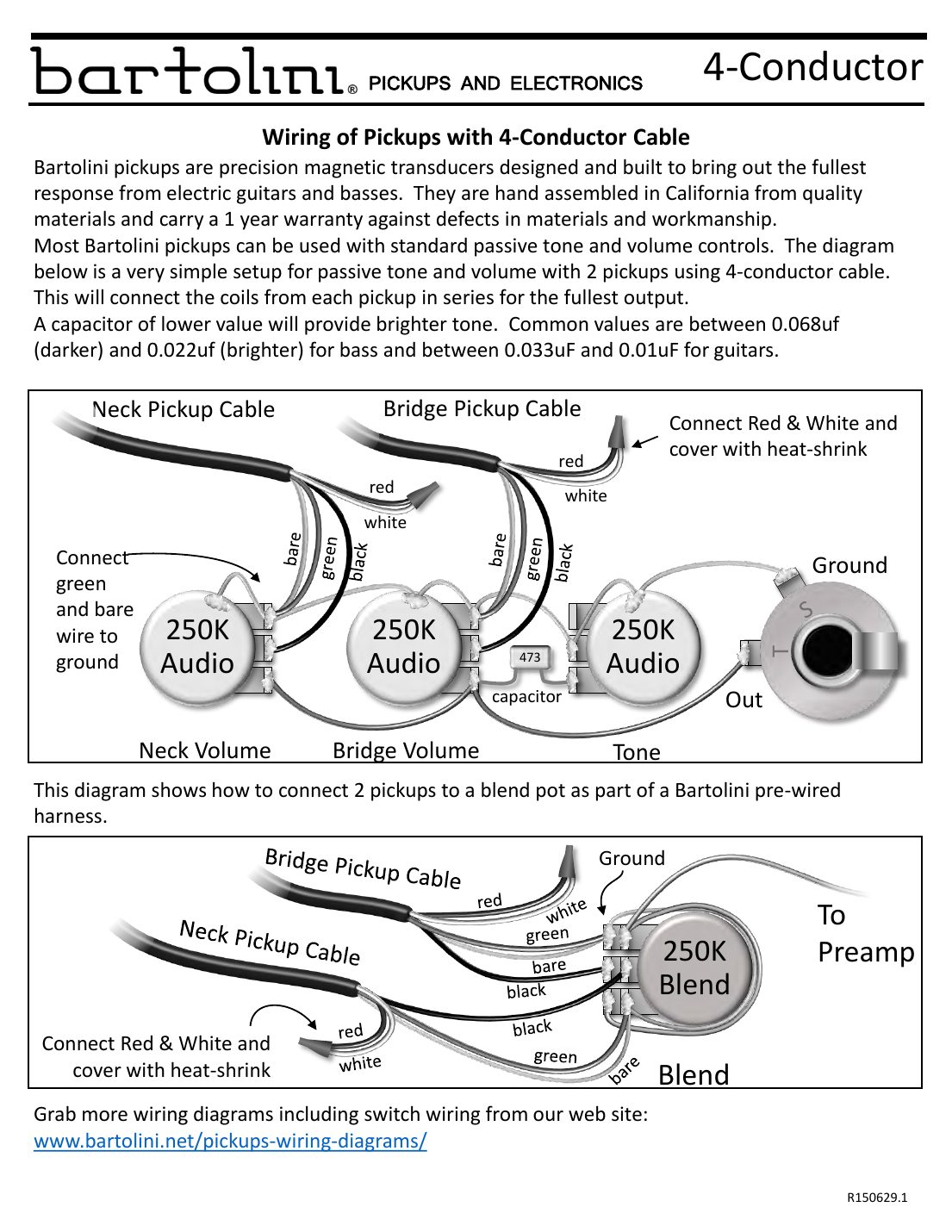
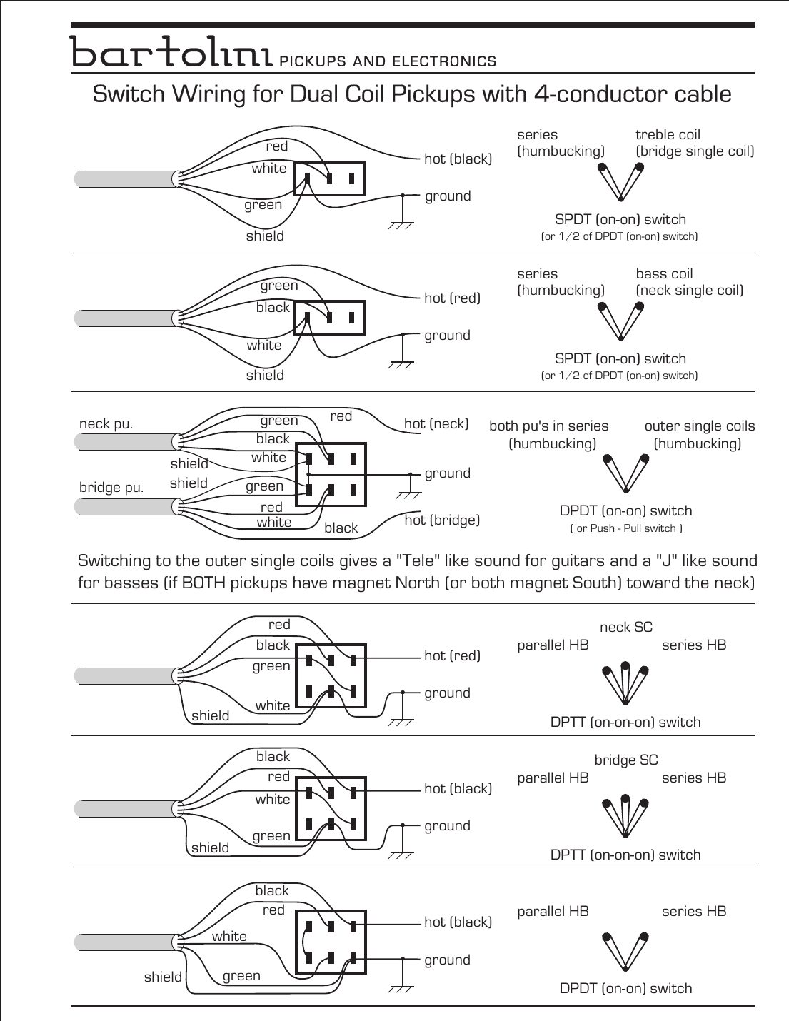
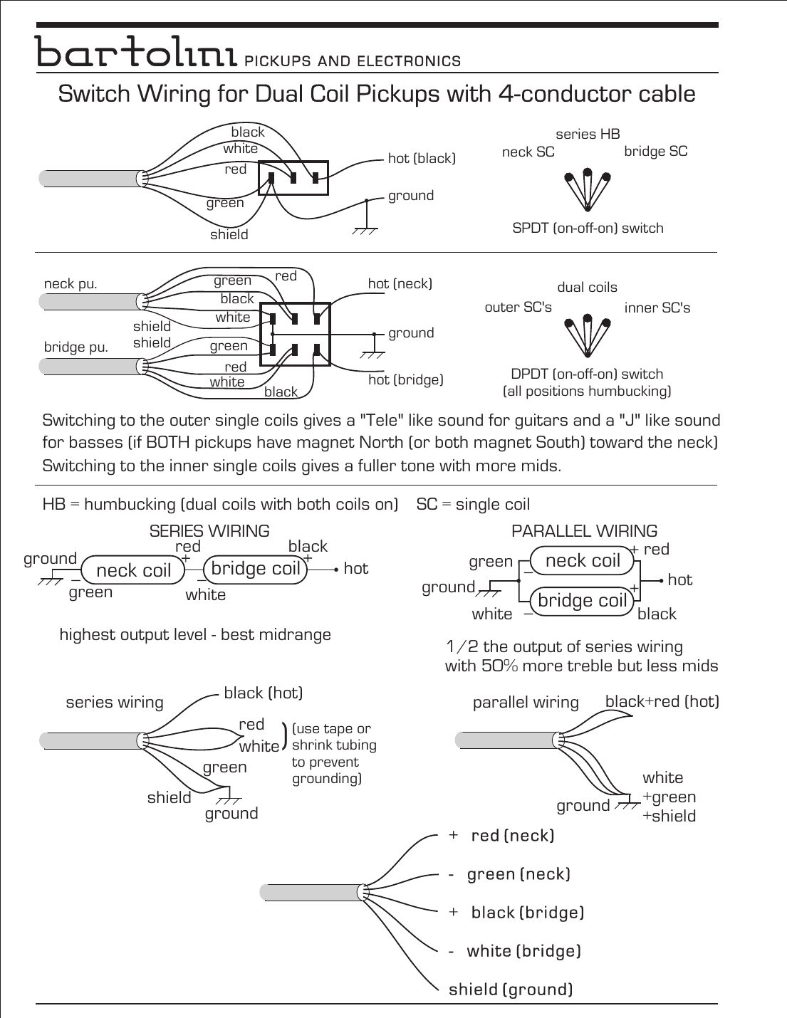
Bartolini dual-coil pickups with 4-conductor cable. Page 1 wires them in series (fullest output) into volume, volume, tone or into a blend; pages 2 and 3 are Bartolini's switch layouts and the colour code.
Controls: 250K audio volumes ×2, 250K audio tone, .047 µF cap, mono jack; switches as listed in the colour-code section.
| # | Wire | Goes to |
|---|---|---|
| 1 | Black | Hot (series) |
| 2 | Red + white | Joined, insulated (series) |
| 3 | Green + bare | Ground |
Wire it with
6-conductor quad-coil pickups: P forward / 4-coil humbucker / P reverse
For Bartolini's quad-coil bass pickups with 6-conductor cable. A DPDT on-off-on switch gives three sounds: P-Bass with the treble coil down, all four coils in series as a humbucker (centre), and P-Bass with the treble coil up.
Controls: DPDT on-off-on mini-toggle; the rest of the controls as for any passive pickup.
| # | Wire | Goes to |
|---|---|---|
| 1 | Black | Pickup output (to the switch, then on to your controls) |
| 2 | White + shield | Ground |
| 3 | Green, orange, blue, red | Switch throws, as drawn |
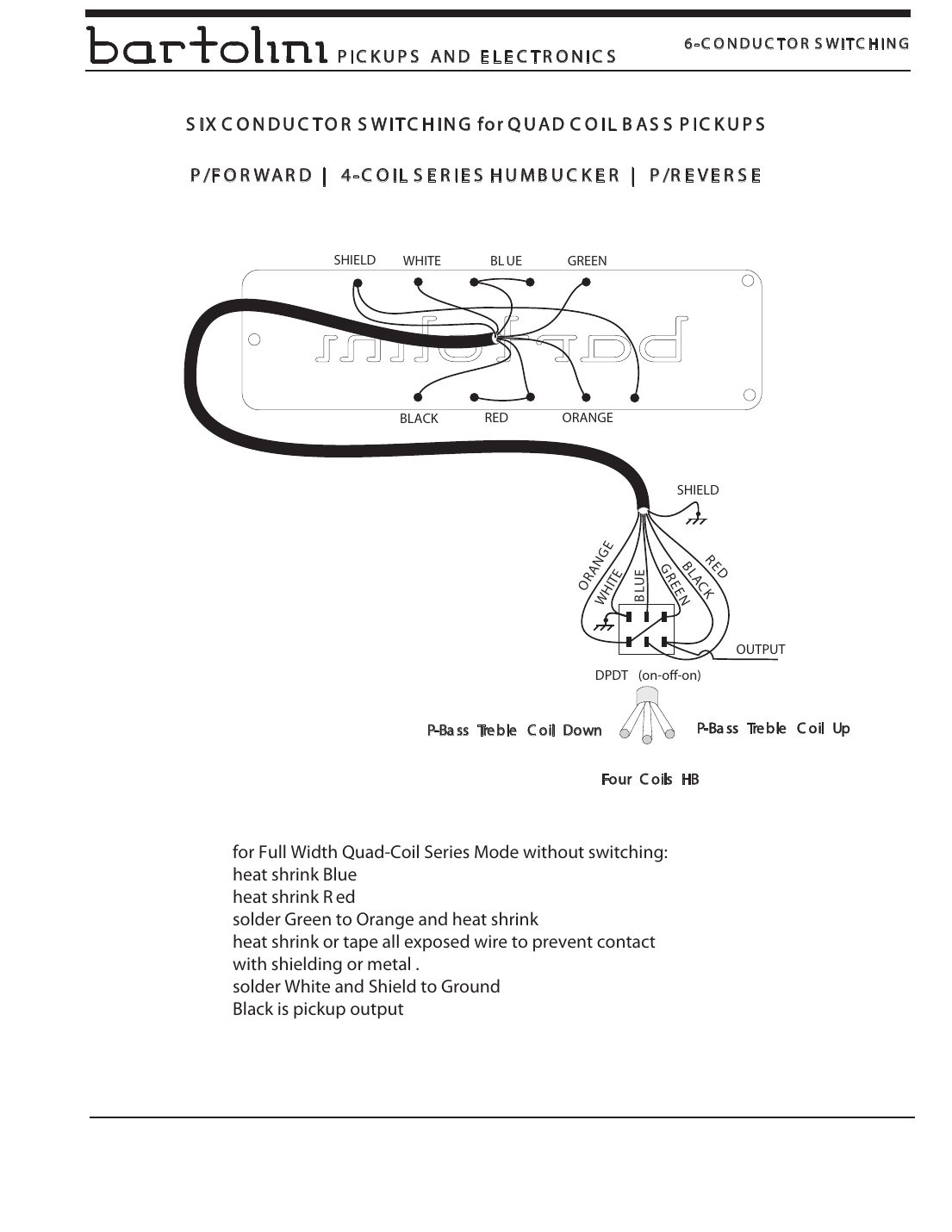
No switch: full-width quad-coil series
- Heat-shrink the blue lead (not used).
- Heat-shrink the red lead (not used).
- Solder green to orange and heat-shrink the joint.
- Solder white and the shield to ground.
- Black is the pickup output: wire it as the hot to your volume.
Tape or heat-shrink every bare end so nothing touches the cavity shielding. FUNCTION-LEVEL for the switch: follow Bartolini's drawing for which lead goes to which lug.
Active pickups
8TC active P-Bass pickup
The 8TC is an active P pickup with its own preamp, giving treble boost and cut on the tone pot. Bartolini shows it alone, with the optional Mid Boost Kit (MBK1, 300 Hz low-mid boost), and with a J treble pickup (9J-L1 or 9V-L) as a P-J.
Controls: 250K audio volume (×2 for P-J), 250K audio tone, .047 or .1 µF treble-cut cap, 750 pF cap at the jack, stereo jack, 9 V battery.
| # | Wire | Goes to |
|---|---|---|
| 1 | Green | Volume pot: outer lug (the 8TC's output) |
| 2 | Red | Battery + (+9 volts) |
| 3 | White | Tone voicing: 'Vintage Tone' (68K + .001 µF to ground) or 'Brightest Tone' (100 pF to ground) |
| 4 | Black | Tone circuit (through 1K + .033 µF; the Mid Boost Kit goes here) |
| 5 | Shield | Ground |
| 6 | Battery − | Stereo jack ring |
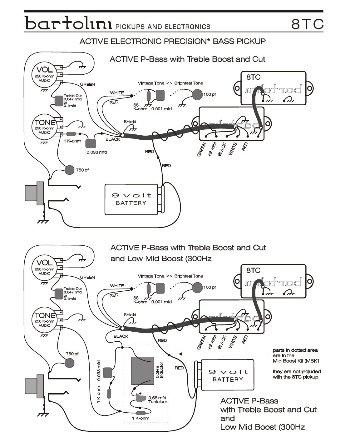
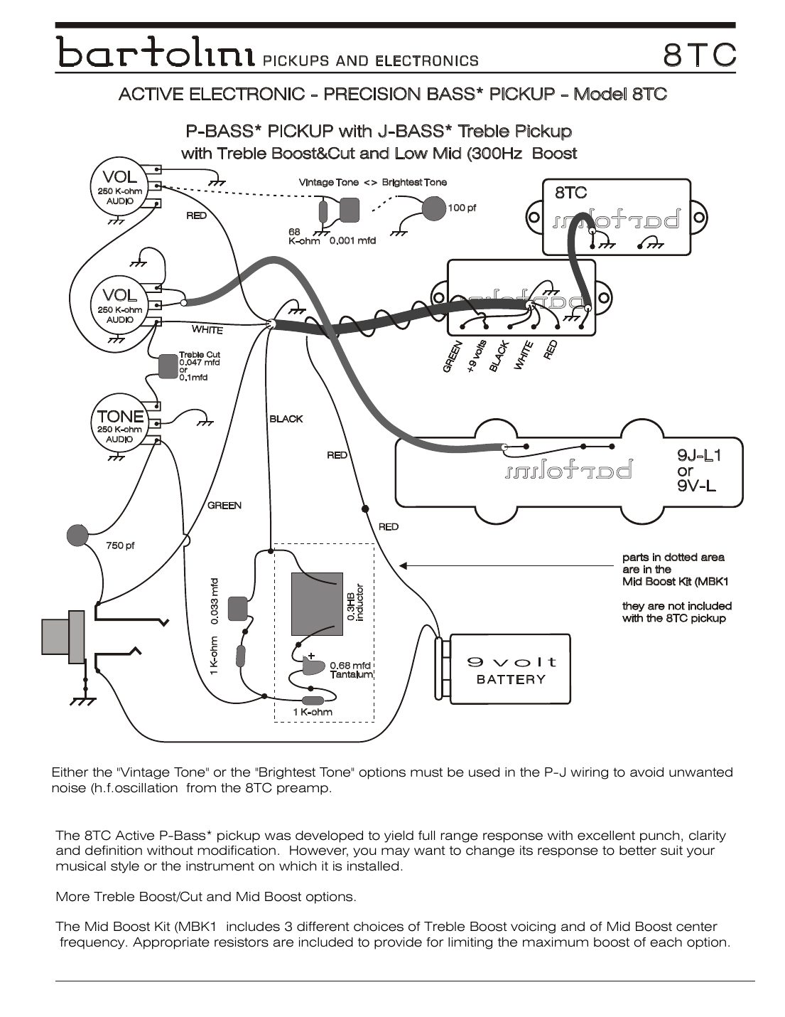
- Volume middle lug to the jack tip; .047 µF (or .1 µF) treble-cut cap between the volume and tone; 750 pF from the jack tip to ground.
- In the P-J version the J pickup goes to its own volume, and Bartolini says either the Vintage Tone or the Brightest Tone option must be fitted, or the 8TC preamp can oscillate (high-frequency noise).
- The Mid Boost Kit (MBK1) isn't included with the 8TC. It has three treble-boost voicings and three mid-boost centre frequencies, with resistors to limit each.
- FUNCTION-LEVEL: this page says what each lead does; follow the drawing for the tone-pot and MBK1 lugs.
Wire it with
9E active Jazz Bass pickups (J pair and P-J)
The 9E is an active J set: the preamp is in the bridge pickup, and the tone pot is a treble boost and cut. Bartolini shows the J pair and a P-J set with an 8T, both with the optional 300 Hz Mid Boost Kit.
Controls: 250K audio volumes ×2, 250K audio tone, .047 or .1 µF treble-cut cap, 750 pF at the jack, stereo jack, 9 V battery.
| # | Wire | Goes to |
|---|---|---|
| 1 | Neck pickup cable | Its own volume (neck) |
| 2 | Red | Bridge coil to the bridge volume |
| 3 | White | Back from the volumes into the 9E preamp |
| 4 | Green | Preamp output toward the jack |
| 5 | +9 volts lead | Battery + |
| 6 | Black | Tone pot: factory on pin 7 (Vintage Tone) |
| 7 | Battery − | Stereo jack ring |
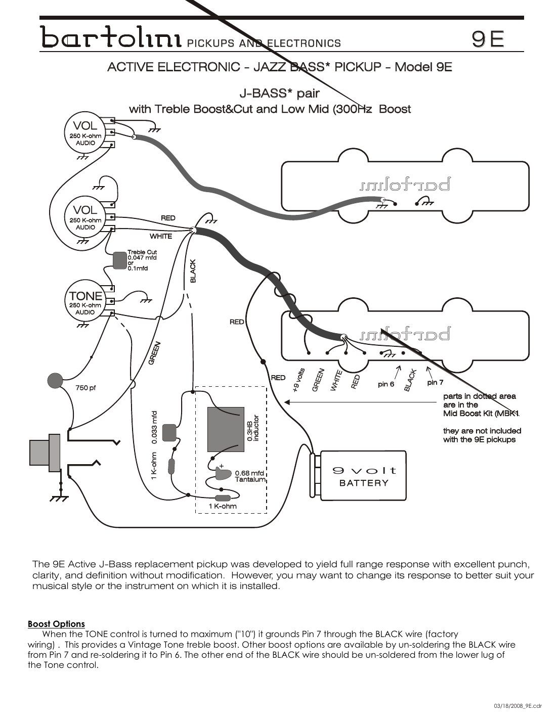
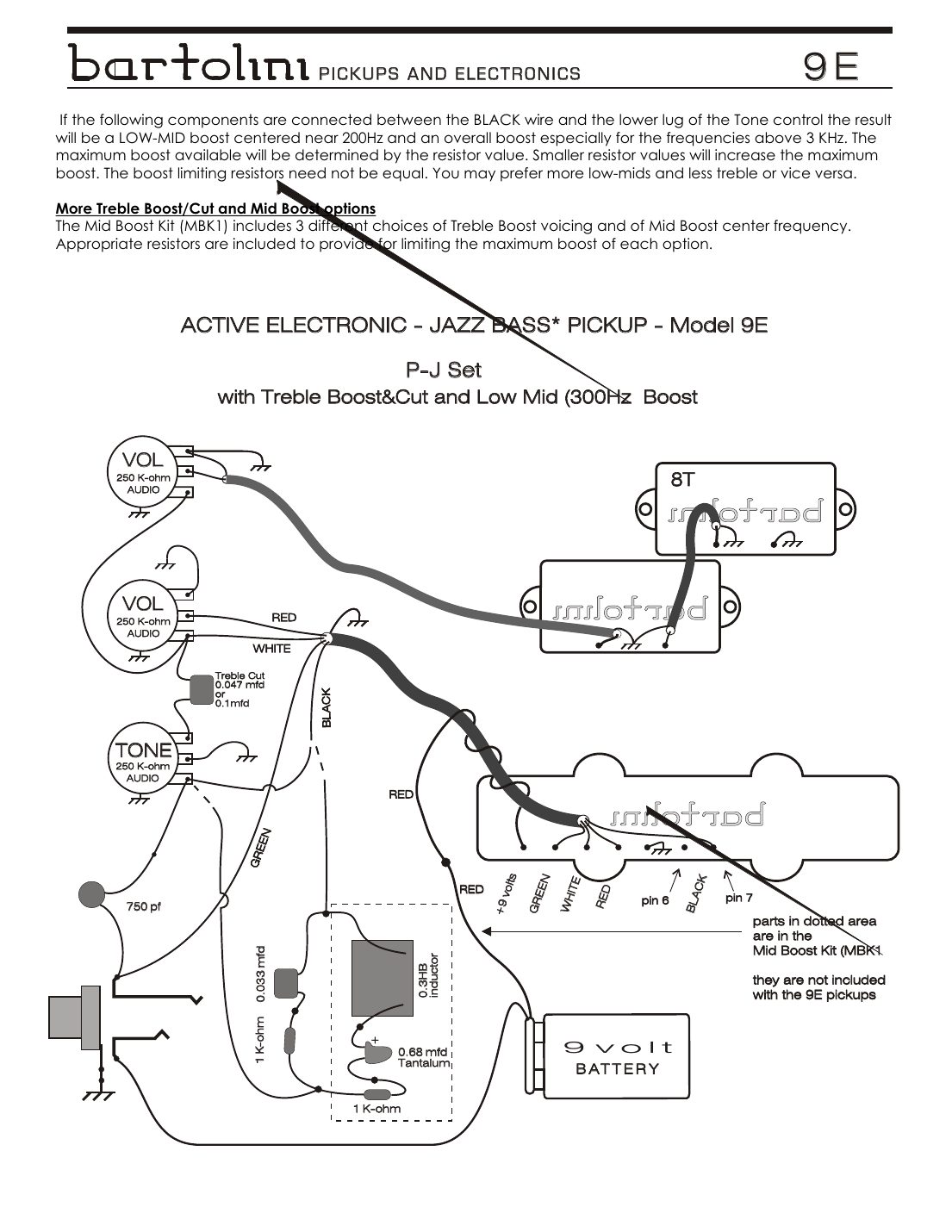
Boost options (from Bartolini's sheet)
- With the tone at 10, the black wire grounds pin 7: that's the factory Vintage Tone treble boost.
- For another voicing, move the black wire from pin 7 to pin 6, and take its other end off the tone pot's lower lug.
- Fitting the Mid Boost Kit parts (1K, .033 µF, .3 H inductor, .68 µF tantalum, 1K) between the black wire and the tone pot's lower lug gives a low-mid boost near 200 Hz plus a boost above 3 kHz. Smaller resistors give more maximum boost; the two limiting resistors don't have to match.
- FUNCTION-LEVEL: follow the drawing for the volume and tone lugs.
9E Jazz Bass with the NTMB 3-band preamp
Two ways to put a 9E pair in front of an NTMB, both with a stacked volume/volume pot (top knob neck, bottom knob bridge).
Controls: Dual stacked 250K audio vol/vol, 47K resistor (active version), NTMB preamp, stereo jack, 9 V battery.
| # | Wire | Goes to |
|---|---|---|
| 1 | 9E stays active: green | Through the stacked vol/vol to NTMB yellow; 47K from yellow to ground |
| 2 | 9E stays active: black | Taped off |
| 3 | 9E stays active: red / white | Stacked vol/vol |
| 4 | 9E passive: white, green, black, red | All taped off (not used) |
| 5 | 9E passive: coils | Stacked vol/vol, then NTMB yellow |
| 6 | NTMB green | Output jack tip |
| 7 | NTMB red | Battery + |
| 8 | Battery − | Stereo jack ring |
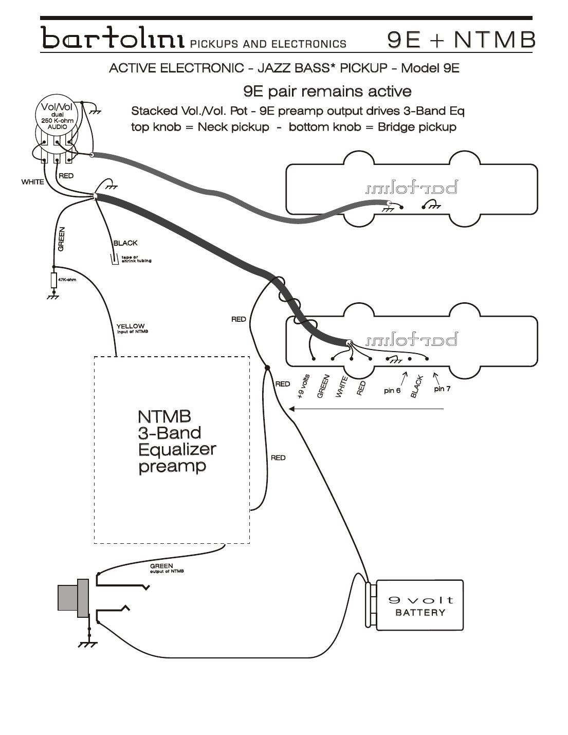
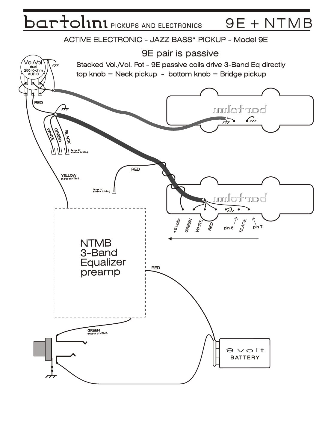
- Active: the 9E's own preamp drives the NTMB. Passive: the 9E coils drive the NTMB directly and the 9E preamp isn't used.
- Neither drawing shows a master volume: the NTMB green goes straight to the jack.
- FUNCTION-LEVEL for the stacked pot lugs.
Wire it with
Controls and jacks
Bartolini blend pot wiring (25K and 250K)
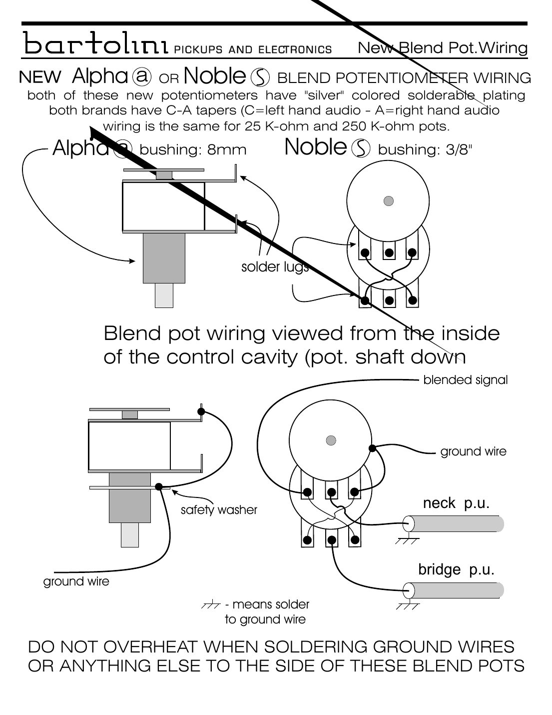
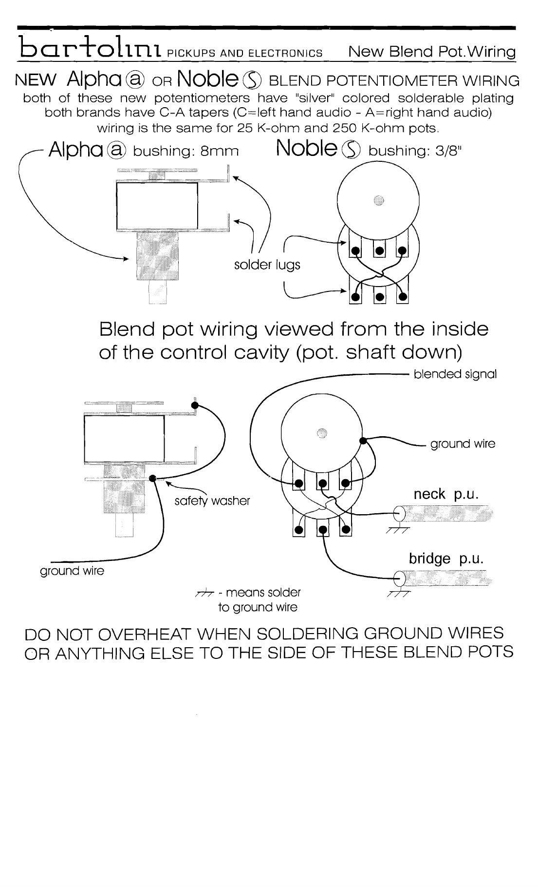
Bartolini's blend pot pinout, viewed from inside the cavity with the shaft down. The older Alpha MN25K had M/N tapers (both pickups full on at the centre detent). The 'new' 250K pot (Noble, after 6/15/00) and the later Alpha and Noble pots have C-A tapers (C = left-hand audio, A = right-hand audio); wiring is the same for 25K and 250K.
Controls: Dual blend pot (25K for active pickups, 250K for passive).
| # | Wire | Goes to |
|---|---|---|
| 1 | Neck pickup hot | One deck's outer lug, as drawn |
| 2 | Bridge pickup hot | The other deck, as drawn |
| 3 | Jumpers between the decks | As drawn (they cross) |
| 4 | Blended signal | The marked lug, on to the volume or preamp input |
| 5 | Ground wire | Pot casing (and the marked lugs) |
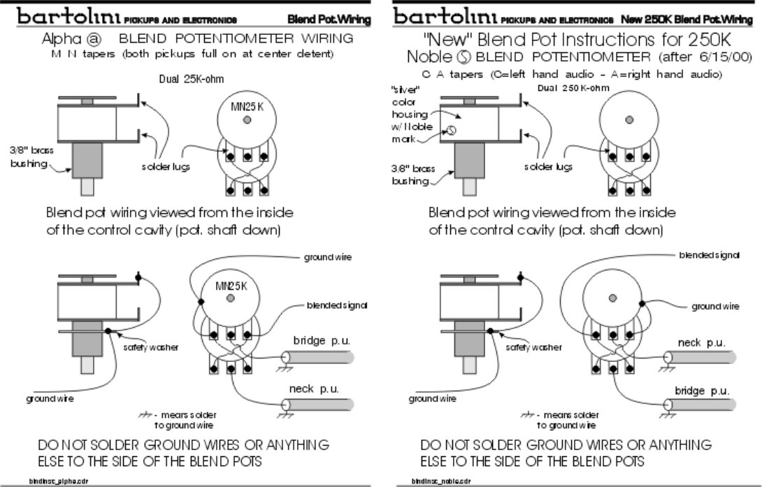
- Bartolini: do not overheat when soldering ground wires or anything else to the side of these blend pots. On the Alpha pot, solder the ground to the safety washer, not the casing.
- Bushings: Alpha 8 mm; Noble 3/8". Old pots are 3/8" brass.
- The same pinout is on page 2 of the NTBT-918 sheet and page 3 of the MPB2-918 sheet.
- FUNCTION-LEVEL: follow the drawing for the lugs.
Wire it with
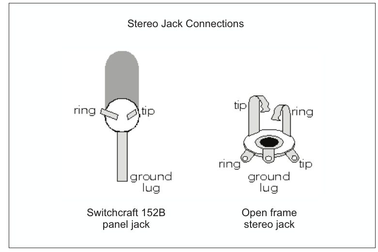
Stereo jack connections
Where tip, ring and ground are on the two stereo jacks Bartolini's diagrams use. Every Bartolini active pickup and preamp needs one: the battery's black goes to the ring, so plugging in turns it on.
Controls: Switchcraft 152B panel jack, or an open-frame stereo jack.
| # | Wire | Goes to |
|---|---|---|
| 1 | Switchcraft 152B: tip | Short lug on one side of the round body |
| 2 | Switchcraft 152B: ring | Short lug on the other side |
| 3 | Switchcraft 152B: ground | The long lug |
| 4 | Open frame: tip and ring | The two spring contacts; each has its own lug on the base |
| 5 | Open frame: ground | Centre lug on the base |
| 6 | Battery − | Ring |
| 7 | Signal | Tip |
| 8 | Ground | Sleeve |
Bartolini MM, MV or DL pickups to Music Man electronics
Fitting a Bartolini MM, MV or DL pickup (4-conductor cable) to the stock Music Man 3-band preamp board. The board keeps its own wiring to the 25K volume, the 50K bass, mid and treble, the jack and the battery.
Controls: The stock Music Man board and pots (volume 25K L, EQ 50K S), stereo jack, 9 V battery.
| # | Wire | Goes to |
|---|---|---|
| 1 | Pickup red, white, black, green, shield | The board's pickup pads, as drawn |
| 2 | Board: battery red / black | Battery; black on to the bridge ground |
| 3 | Board: jack | As before |
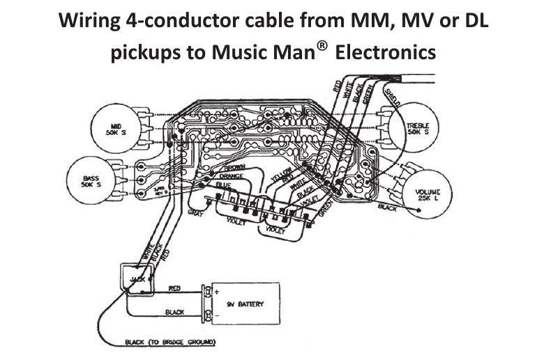
- The drawing is a small scan of the Music Man board, so this page doesn't name pad by pad. Bartolini's colour code still applies (red/green one coil, black/white the other, shield ground): see the colour-code section.
- FUNCTION-LEVEL: follow the drawing for which pad each lead goes to, or call us.
Wire it with
Preamps
Active/passive switch on NTBT and NTMB preamps
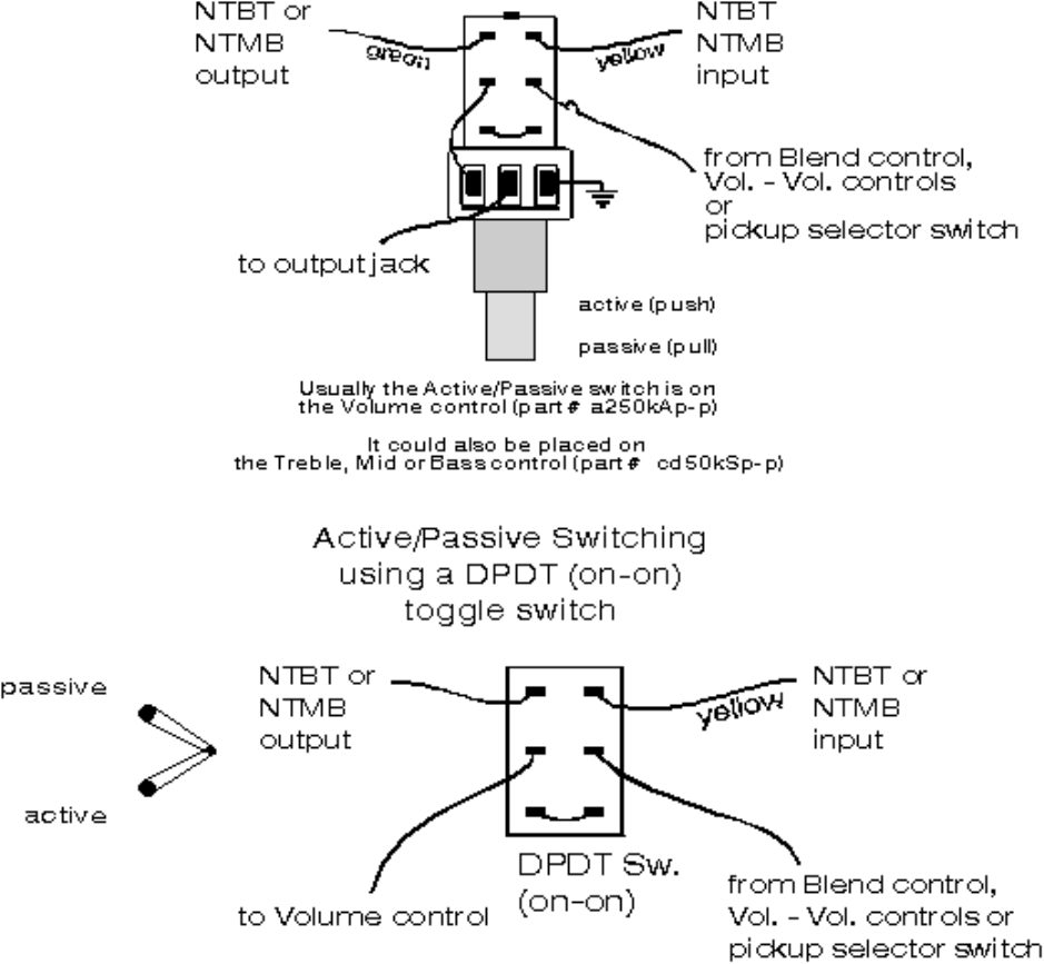
Bartolini's active/passive switching for the NTBT and NTMB: on a push/pull pot (usually the volume, part a250kAp-p, or an EQ pot, cd50kSp-p) or a DPDT on-on toggle.
Controls: Push/pull pot or DPDT on-on mini-toggle.
| # | Wire | Goes to |
|---|---|---|
| 1 | Preamp green (output) | Switch: active end, one side |
| 2 | Preamp yellow (input) | Switch: active end, other side |
| 3 | From blend / vol-vol / pickup selector | Switch: middle lug under the yellow |
| 4 | To volume (or output jack) | Switch: middle lug under the green |
| 5 | Jumper | Across the two passive-end lugs |
Wire it with
NTMB-918 3-band preamp (9 V or 18 V)
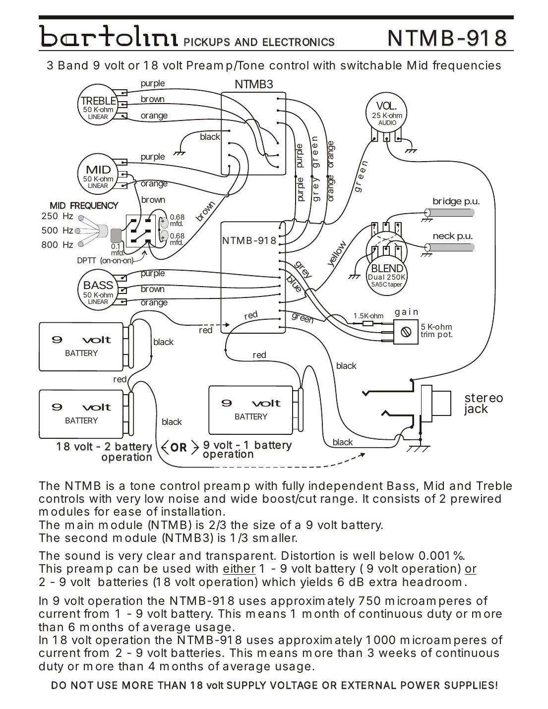
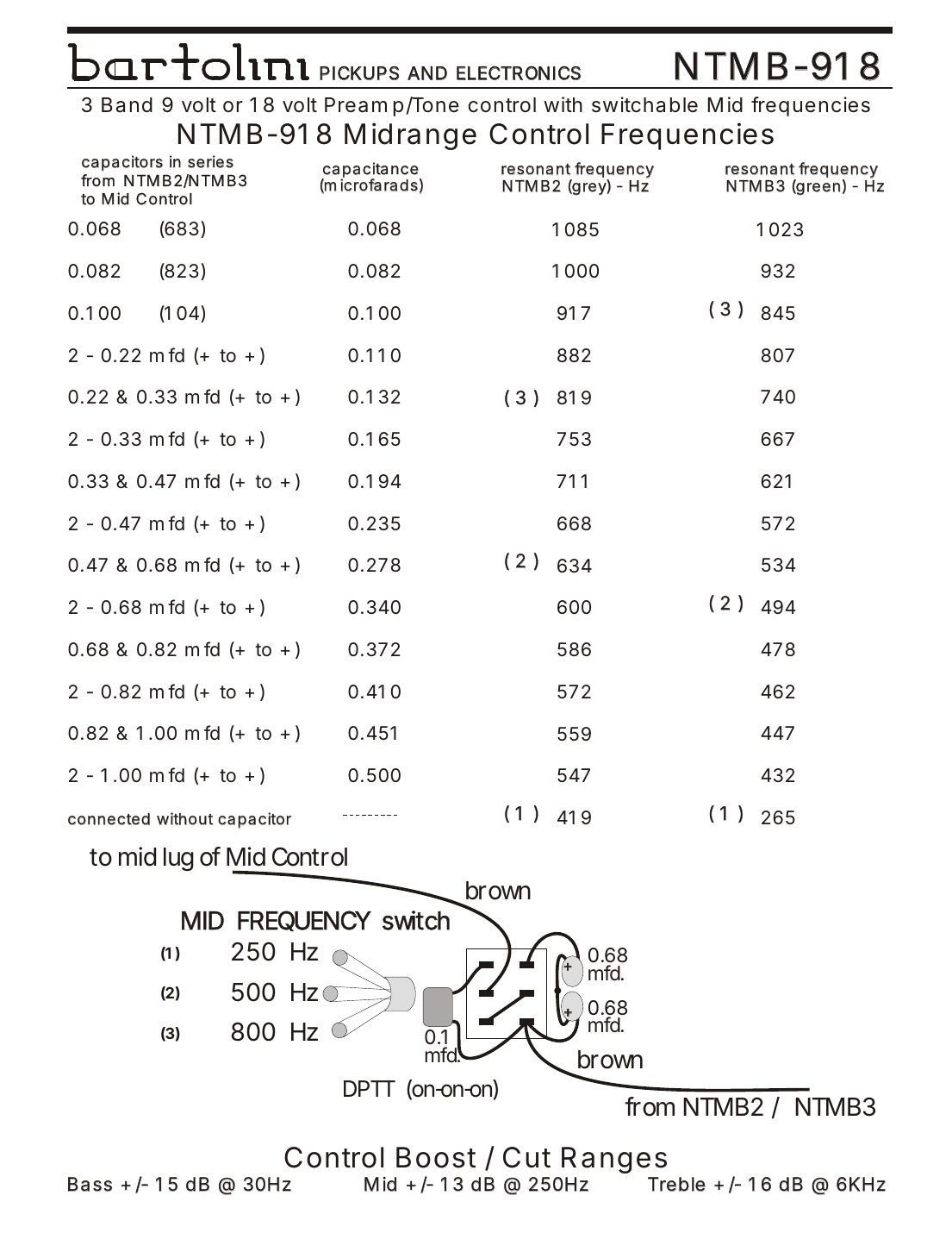
Bartolini's NTMB-918: bass, mid and treble with switchable mid frequency, in two pre-wired modules (NTMB, about 2/3 the size of a 9 V battery, and NTMB3, a third smaller). Distortion is under .001%.
Controls: 25K audio volume, 50K linear treble, mid and bass, dual 250K 5A5C blend, DPTT on-on-on mid switch with 2 × .68 µF and .1 µF, 5K gain trim + 1.5K, stereo jack, one or two 9 V batteries.
| # | Wire | Goes to |
|---|---|---|
| 1 | Yellow | Blend output (preamp input) |
| 2 | Green | Volume (output) |
| 3 | Red | Battery + |
| 4 | Black | Ground |
| 5 | Purple / brown / orange | Treble, mid and bass pots |
| 6 | Brown (from NTMB2/NTMB3) | Mid frequency switch |
| 7 | Grey / blue | Gain trim |
Mid frequencies and ranges
- Boost/cut: bass ±15 dB at 30 Hz, mid ±13 dB at 250 Hz, treble ±16 dB at 6 kHz.
- The stock mid switch: position (1) 250 Hz, (2) 500 Hz, (3) 800 Hz, marked in the table.
- Current: about 750 µA on 9 V (a month continuous, 6+ months of average use); about 1,000 µA on 18 V (3+ weeks continuous, 4+ months average). 18 V gives 6 dB more headroom.
| Capacitor(s), µF | Total µF | NTMB2 (grey), Hz | NTMB3 (green), Hz |
|---|---|---|---|
| 0.068 (683) | 0.068 | 1085 | 1023 |
| 0.082 (823) | 0.082 | 1000 | 932 |
| 0.100 (104) | 0.100 | 917 | 845 (3) |
| 2 × 0.22 (+ to +) | 0.110 | 882 | 807 |
| 0.22 & 0.33 (+ to +) | 0.132 | 819 (3) | 740 |
| 2 × 0.33 (+ to +) | 0.165 | 753 | 667 |
| 0.33 & 0.47 (+ to +) | 0.194 | 711 | 621 |
| 2 × 0.47 (+ to +) | 0.235 | 668 | 572 |
| 0.47 & 0.68 (+ to +) | 0.278 | 634 (2) | 534 |
| 2 × 0.68 (+ to +) | 0.340 | 600 | 494 (2) |
| 0.68 & 0.82 (+ to +) | 0.372 | 586 | 478 |
| 2 × 0.82 (+ to +) | 0.410 | 572 | 462 |
| 0.82 & 1.00 (+ to +) | 0.451 | 559 | 447 |
| 2 × 1.00 (+ to +) | 0.500 | 547 | 432 |
| No capacitor | — | 419 (1) | 265 (1) |
Wire it with
NTBT-918 2-band preamp (9 V or 18 V)
The NTBT-918 is the NTMB without the mid: independent bass and treble on one module, about 2/3 the size of a 9 V battery. Page 2 is the blend pot pinout.
Controls: 25K audio volume, 50K linear treble and bass, dual 250K 5A5C blend, 5K gain trim + 1.5K, stereo jack, one or two 9 V batteries.
| # | Wire | Goes to |
|---|---|---|
| 1 | Yellow | Blend output (preamp input) |
| 2 | Green | Volume (output) |
| 3 | Red | Battery + |
| 4 | Black | Ground |
| 5 | Purple / brown / orange | Treble and bass pots |
| 6 | Grey / blue / white | Gain trim |
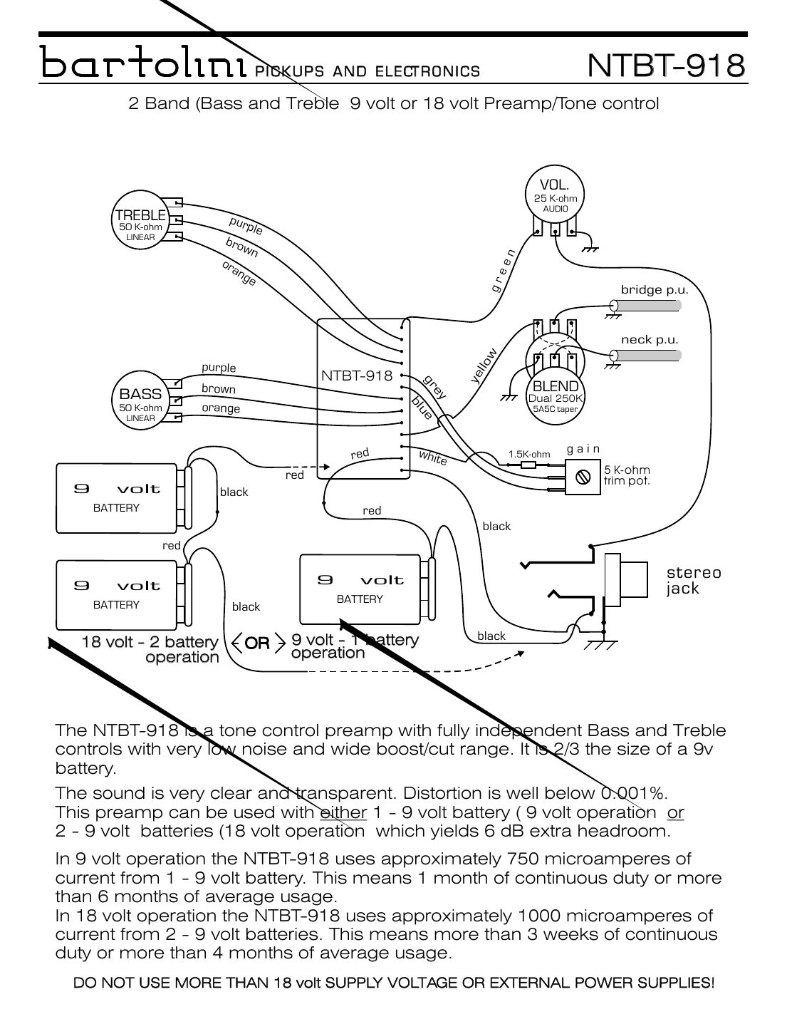
- Current draw is the same as the NTMB: about 750 µA on 9 V (a month continuous, 6+ months of average use) and about 1,000 µA on 18 V.
- The published PDF has a few stray diagonal lines across the drawing; they aren't wires.
Wire it with
MPB2-918 piezo buffer (with an NTMB)
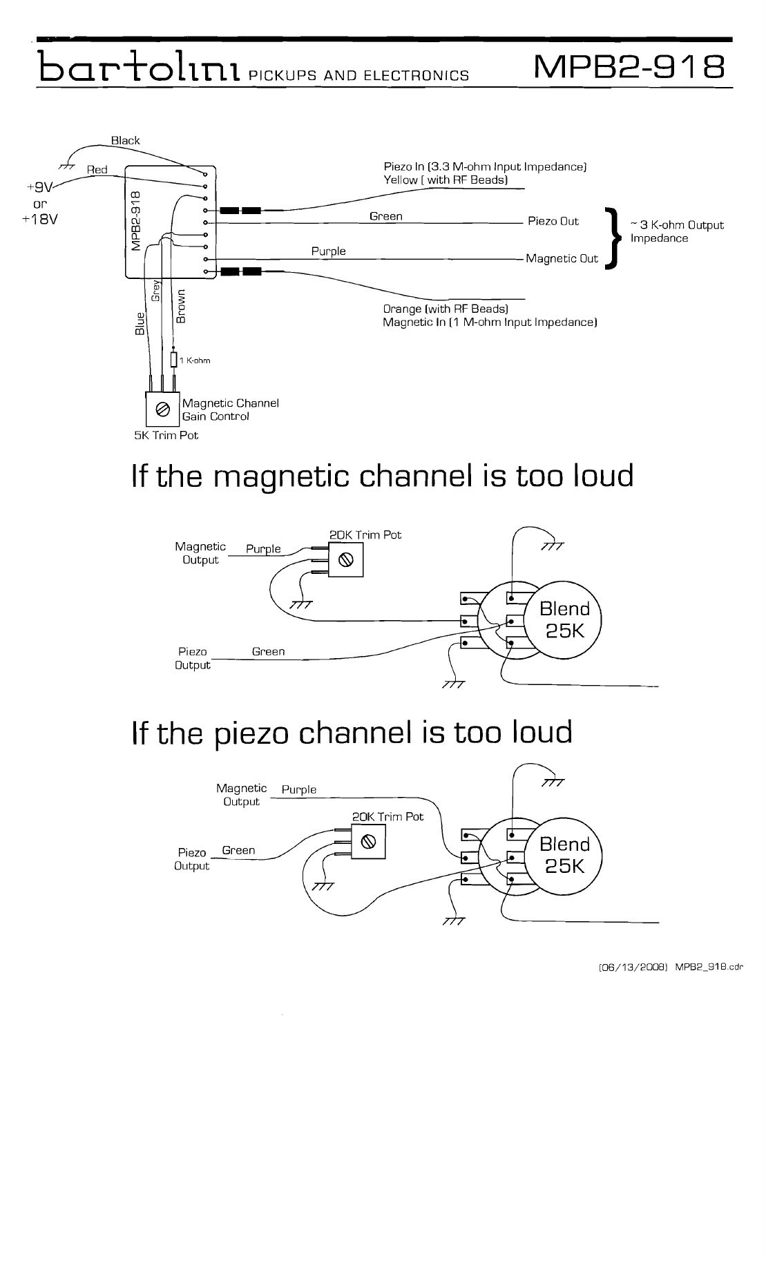
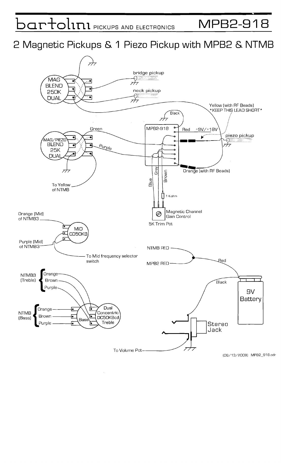
The MPB2-918 buffers a piezo pickup and a magnetic pickup so they can be blended into one preamp. Bartolini shows the buffer's leads, two fixes for an unbalanced blend, and a full 2 magnetic + 1 piezo layout with an NTMB.
Controls: MPB2-918, dual 250K mag blend, dual 25K mag/piezo blend, 5K gain trim + 1K, CD50KB mid, DC50KBcd concentric bass/treble, stereo jack, 9 V battery (or 18 V).
| # | Wire | Goes to |
|---|---|---|
| 1 | Black | Ground |
| 2 | Red | +9 V or +18 V (joined with the NTMB red to battery +) |
| 3 | Yellow (RF beads) | Piezo in, 3.3 M-ohm. Keep this lead short |
| 4 | Orange (RF beads) | Magnetic in, 1 M-ohm: from the mag blend output |
| 5 | Green | Piezo out (about 3K output impedance) |
| 6 | Purple | Magnetic out |
| 7 | Blue / grey / brown (+1K) | 5K trim pot: magnetic channel gain |
| 8 | Mag/piezo blend output | NTMB yellow |
| 9 | Battery − | Stereo jack ring |
If one channel is too loud
- Magnetic too loud: put a 20K trim pot in the purple (magnetic out) line before the 25K blend, its third lug to ground.
- Piezo too loud: the same 20K trim in the green (piezo out) line.
- With the NTMB: NTMB3 orange and purple go to the CD50KB mid pot; the NTMB (bass) and NTMB3 (treble) orange/brown/purple go to the two sections of the DC50KBcd concentric pot; the mid pot also goes to the mid frequency selector.
- FUNCTION-LEVEL for the blend pot lugs: follow the drawing.
Wire it with
Active/passive switch for TCT, NTCT and XTCT preamps
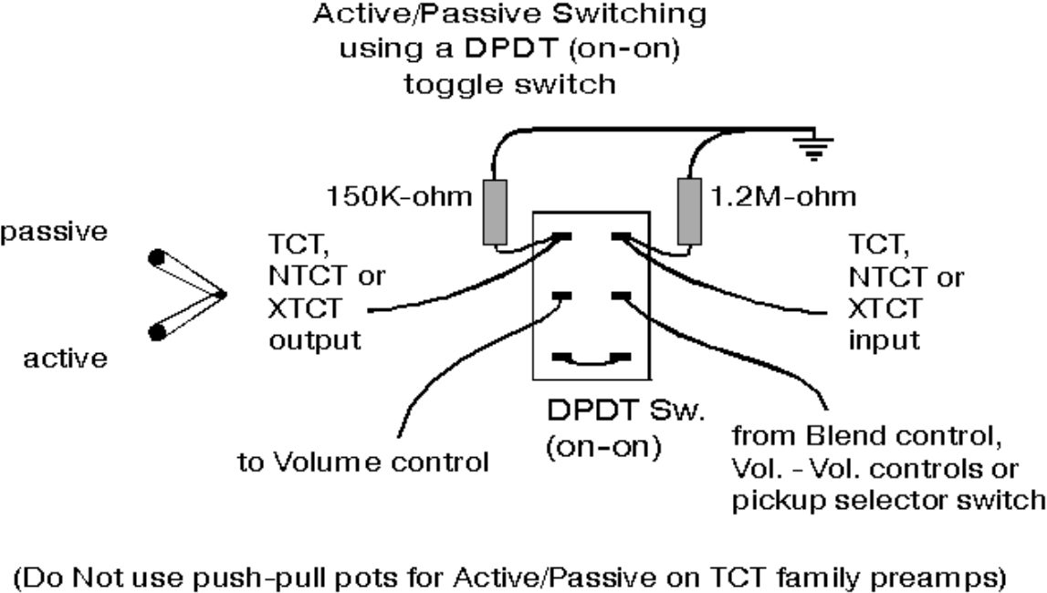
The TCT family needs a toggle and two resistors to switch cleanly. Bartolini: do not use push/pull pots for active/passive on TCT-family preamps.
Controls: DPDT on-on toggle, 150K and 1.2M resistors.
| # | Wire | Goes to |
|---|---|---|
| 1 | TCT output | Switch: active end; 150K from this lug to ground |
| 2 | TCT input | Switch: active end, other side; 1.2M from this lug to ground |
| 3 | To volume | Middle lug under the output |
| 4 | From blend / vol-vol / selector | Middle lug under the input |
| 5 | Jumper | Across the passive-end lugs |
Wire it with
Volume, volume, tone with the Bartolini TC3 (BBG diagram)
Best Bass Gear's own drawing for a 2-pickup bass with two volumes, a tone pot and a Bartolini TC3 preamp.
Controls: 250K volumes ×2, tone pot and cap, Bartolini TC3, stereo jack, 9 V battery.
| # | Wire | Goes to |
|---|---|---|
| 1 | Neck hot | Volume 1: middle lug |
| 2 | Neck ground | Volume 1 casing |
| 3 | Bridge hot | Volume 2: middle lug |
| 4 | Bridge ground | Volume 2 casing |
| 5 | Volume 1 and 2: right-hand lugs (yellow) | Joined, to the tone pot middle lug and the TC3 yellow (input) |
| 6 | Volume 1 and 2: left-hand lugs | Ground |
| 7 | Tone cap | Tone pot left lug to its casing |
| 8 | Tone casing | Jack ground lug (sleeve), and ground to shielding |
| 9 | TC3 green | Jack tip |
| 10 | TC3 red | Battery + |
| 11 | TC3 black (and grey) | Ground |
| 12 | TC3 blue | Insulated, not used (capped on the drawing) |
| 13 | Battery − | Jack ring (stereo jack) |
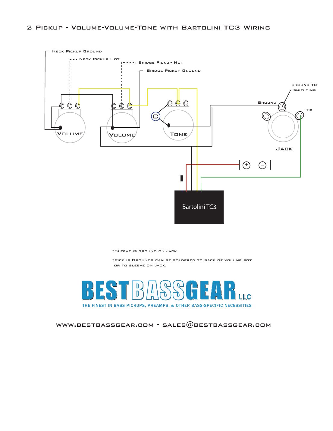
- Sleeve is ground on the jack. Pickup grounds can go to the back of a volume pot or to the jack sleeve.
- The drawing puts each pickup's hot on the volume's middle lug and takes the output from the outer lug: follow it as drawn.
The hookups
Passive, two pickups: volume, volume, master tone
Bartolini's basic passive layout for any of their passive pickups: each pickup has its own 250K volume, the two volume outputs are joined, and one master tone and the jack follow. It's the top drawing on both the 1-conductor and 4-conductor sheets.
You need: 3 × 250K audio pots, a .047 µF cap (Bartolini draws a '473'), mono output jack, hookup wire, bridge ground wire.
| # | From | To | Notes |
|---|---|---|---|
| 1 | Neck pickup: hot (clear on 1-conductor cable; black on 4-conductor) | Neck volume: MIDDLE lug | Bartolini puts the hot on the middle lug, not an outer lug |
| 2 | Neck pickup: ground (braid; or green + bare) | Neck volume: the outer lug nearest the cable, then on to the casing | Ground |
| 3 | Bridge pickup: hot | Bridge volume: MIDDLE lug | |
| 4 | Bridge pickup: ground | Bridge volume: outer lug nearest the cable, then to its casing | |
| 5 | 4-conductor only: red + white of each pickup | Each other, nowhere else | Solder together and cover with heat-shrink. That puts the two coils in series |
| 6 | Neck volume: other outer lug | Bridge volume: same outer lug | Joins the two volume outputs |
| 7 | Bridge volume: that outer lug | Output jack: tip ('T') | Hot out |
| 8 | Bridge volume: that outer lug | .047 µF cap ('473'), then the tone pot middle lug | Cap in series with the tone pot |
| 9 | Tone pot: outer lug nearest the cap side | Tone casing | Ground; the third tone lug is unused |
| 10 | Ground wire | Casing to casing, all three pots | |
| 11 | Output jack: sleeve ('S') | Tone pot casing | Ground |
| 12 | Ground wire from the bridge | Any pot casing | String ground (not on Bartolini's drawing, but fit it) |
Step by step
- On 4-conductor cable, first join red and white of each pickup and heat-shrink them.
- Solder each pickup's hot (clear or black) to the middle lug of its volume pot, and its ground (braid, or green + bare) to the outer lug on the cable side; link that lug to the pot casing.
- Join the other outer lugs of the two volumes, and run that line on to the jack tip.
- From the same line, solder the .047 µF cap to the tone pot's middle lug; ground one outer lug of the tone pot.
- Link all three casings, solder the jack sleeve to the tone casing and the bridge ground wire to any casing. Test before you close up.
- Bartolini's cap range: .068 µF (darker) to .022 µF (brighter) for bass; .033 to .01 µF for guitar.
- Hot on the middle lug and output from the outer lug is how Bartolini draws it: each volume can go to zero without killing the other pickup. A stock Jazz Bass does it the other way round, and either works.
- Sheets that use this hookup: 1-conductor (coax) pickups: volume, volume, tone or blend, 4-conductor pickups: series, parallel and switching.
Two pickups into a Bartolini blend pot (pre-wired harness)
The bottom drawing on the 1-conductor and 4-conductor sheets: the two pickups go to the dual 250K blend pot of a Bartolini pre-wired harness, and the harness's yellow wire takes the blended signal to the preamp.
You need: A Bartolini pre-wired harness with a 250K blend pot (or a dual 250K C-A taper blend), heat-shrink.
| # | From | To | Notes |
|---|---|---|---|
| 1 | Neck pickup: hot (clear, or black on 4-conductor) | Blend pot: the neck input lug | One deck of the blend |
| 2 | Bridge pickup: hot (clear, or black on 4-conductor) | Blend pot: the bridge input lug | The other deck |
| 3 | Both pickups: ground (braid, or green + bare) | Blend pot casing / harness ground | |
| 4 | 4-conductor only: red + white of each pickup | Each other, insulated | Coils in series |
| 5 | Harness yellow | Already on the blend output | Goes to the preamp input |
Step by step
- Prepare each pickup: on 4-conductor cable join red and white and heat-shrink them.
- Solder the neck hot and the bridge hot to the blend pot's input lugs as drawn (one on each deck).
- Solder both grounds to the blend pot's ground point. Don't overheat the blend pot's casing (see the blend pot section).
- FUNCTION-LEVEL: Bartolini's drawing is clear about which wire goes to the blend, not which lug number. Follow the drawing for the lugs, or the blend pot pinout section below.
- Sheets that use this hookup: 1-conductor (coax) pickups: volume, volume, tone or blend, 4-conductor pickups: series, parallel and switching, Bartolini blend pot wiring (25K and 250K).
Bartolini 4-conductor colour code: series, parallel and single coil
Every Bartolini dual-coil pickup with 4-conductor cable uses the same colour code. Page 3 of the 4-conductor sheet sets it out, and it's what every switch layout on pages 2 and 3 is built from.
You need: Heat-shrink or tape; for switching, an SPDT/DPDT mini-toggle or a push/pull pot.
| # | From | To | Notes |
|---|---|---|---|
| 1 | Red | Neck-side coil: + (start) | |
| 2 | Green | Neck-side coil: − (finish) | |
| 3 | Black | Bridge-side coil: + (start) | |
| 4 | White | Bridge-side coil: − (finish) | |
| 5 | Shield (bare) | Ground | Always |
| 6 | SERIES (humbucking): black | Hot | Highest output, best midrange |
| 7 | SERIES: red + white | Each other, insulated | Tape or heat-shrink so they can't touch ground |
| 8 | SERIES: green + shield | Ground | |
| 9 | PARALLEL (humbucking): black + red | Hot | About half the output of series, 50% more treble, less mids |
| 10 | PARALLEL: white + green + shield | Ground | |
| 11 | SINGLE COIL, bridge-side: black | Hot | White + green + shield to ground; red insulated |
| 12 | SINGLE COIL, neck-side: red | Hot | Green + shield to ground; black and white insulated |
Step by step
- Decide on series, parallel or a switch. For series, join red and white, insulate them, take black as hot and green + shield to ground.
- For parallel, twist black and red together as hot and white, green and shield together as ground.
- For a switch, follow the layout for your switch on pages 2 and 3 of the sheet: the commons go to hot and ground, and the coil ends go to the throws.
- Bartolini's switch layouts on pages 2 and 3: series / bridge single coil (SPDT on-on); series / neck single coil (SPDT on-on); both pickups in series / outer single coils (DPDT on-on or push-pull); parallel / neck SC / series (DPTT on-on-on); parallel / bridge SC / series (DPTT on-on-on); parallel / series (DPDT on-on); neck SC / series / bridge SC (SPDT on-off-on); outer SCs / dual coils / inner SCs (DPDT on-off-on, all positions humbucking).
- Outer single coils give a 'J' sound on bass only if both pickups have the same magnet polarity (both North or both South) toward the neck. Inner single coils give a fuller tone with more mids.
- FUNCTION-LEVEL for the switch lugs: the page gives what each position does and which wires go to the switch; follow Bartolini's drawing for the lug-by-lug layout.
- Sheets that use this hookup: 4-conductor pickups: series, parallel and switching, Bartolini MM, MV or DL pickups to Music Man electronics.
NTMB-918 and NTBT-918 preamps: the harness, colour by colour
Bartolini's NTMB (3-band) and NTBT (2-band) come pre-wired with colour-coded leads. Each EQ pot takes purple, brown and orange; yellow is the input, green the output; red and black are power and ground.
You need: 25K audio volume, dual 250K 5A5C blend (if two pickups), 50K linear EQ pots (pre-wired), stereo output jack, one 9 V battery (or two for 18 V).
| # | From | To | Notes |
|---|---|---|---|
| 1 | EQ pots: purple / brown / orange | Top / middle / bottom lug of each EQ pot, as drawn | Treble, (mid), bass. Pre-wired on the stock harness |
| 2 | Yellow | Blend pot output (or a single pickup's hot, or the A/P switch) | Preamp input |
| 3 | Green | Volume pot (25K audio): outer lug | Preamp output. Volume middle lug goes to the jack tip |
| 4 | Red | Battery + (red snap) | 9 V; for 18 V, two batteries in series |
| 5 | Black | Ground | |
| 6 | Battery − (black snap) | Stereo jack: ring | Plugging in turns the preamp on |
| 7 | Grey / blue (+ 1.5K resistor) | 5K gain trim pot | Sets the preamp's gain; follow the drawing for the lugs |
| 8 | NTMB only: brown from the NTMB2/NTMB3 modules | Mid frequency switch (DPTT on-on-on) | 250 / 500 / 800 Hz with 2 × .68 µF and .1 µF caps |
| 9 | Bridge and neck pickup hots | Dual 250K blend pot inputs | Grounds to the blend casing |
| 10 | Jack sleeve | Ground |
Step by step
- Mount the pots and the stereo jack. Wire the pickups to the blend pot.
- Solder the preamp's yellow to the blend output and green to the volume pot's outer lug; run the volume's middle lug to the jack tip and its other outer lug to ground.
- Solder the preamp's black to ground and red to the battery's red. Battery black goes to the jack ring.
- For 18 V, connect two batteries in series (red of one to black of the other) as drawn: never more than 18 V and never an external supply.
- Set the gain trim by ear with the EQ flat, so active and passive are a similar level.
- FUNCTION-LEVEL for the gain trim and the NTMB3 module: the drawing shows which leads go there; follow it for the lugs.
- Bartolini's warning: do not use more than 18 V or an external power supply.
- Sheets that use this hookup: 8TC active P-Bass pickup, 9E Jazz Bass with the NTMB 3-band preamp, NTMB-918 3-band preamp (9 V or 18 V), NTBT-918 2-band preamp (9 V or 18 V), MPB2-918 piezo buffer (with an NTMB).
Active/passive switch on Bartolini preamps (push/pull or DPDT toggle)
A DPDT switch (the switch on a push/pull pot, or an on-on toggle) either sends the pickups through the preamp, or jumps straight past it to the volume.
You need: DPDT on-on mini-toggle, or a push/pull pot (Bartolini part a250kAp-p for volume, cd50kSp-p for an EQ pot); for TCT-family preamps a toggle plus 150K and 1.2M resistors.
| # | From | To | Notes |
|---|---|---|---|
| 1 | Middle lug, side A | To the volume control (or the output jack on a push/pull volume) | Common |
| 2 | Middle lug, side B | From the blend control, vol/vol controls or pickup selector | Common |
| 3 | End lug, side A (active end) | Preamp output: green | |
| 4 | End lug, side B (active end) | Preamp input: yellow | |
| 5 | Other end lugs, A and B | Each other (jumper) | Bypass path for passive |
| 6 | TCT, NTCT, XTCT only: preamp output lug | 150K resistor to ground | Keeps it quiet when switched |
| 7 | TCT, NTCT, XTCT only: preamp input lug | 1.2M resistor to ground |
Step by step
- Solder a jumper between the two end lugs at one end of the switch.
- At the other end, solder the preamp output (green) to one side and the preamp input (yellow) to the other.
- Middle lugs: the side under the green goes on to the volume; the side under the yellow comes from your blend pot or pickup selector.
- For a TCT-family preamp, add 150K from the output lug and 1.2M from the input lug to ground.
- On Bartolini's push/pull: push = active, pull = passive.
- Bartolini: don't use push/pull pots for active/passive on TCT-family preamps. Use a toggle.
- In passive, the preamp's EQ does nothing and the battery isn't used for the signal.
- Sheets that use this hookup: Active/passive switch on NTBT and NTMB preamps, NTMB-918 3-band preamp (9 V or 18 V), NTBT-918 2-band preamp (9 V or 18 V), Active/passive switch for TCT, NTCT and XTCT preamps.
FAQ
Which wire is hot on a Bartolini 4-conductor pickup?
For series (Bartolini's standard, fullest output), black is hot, red and white are soldered together and insulated, and green and the bare shield go to ground. For parallel, black and red together are hot and white, green and shield are ground.
What value pots do Bartolini pickups and preamps use?
Passive pickups use 250K audio volume and tone pots. The NTMB and NTBT preamps use a 25K audio volume, 50K linear EQ pots and a dual 250K (5A5C) blend. Active Bartolini pickups like the 8TC and 9E use 250K volume and tone.
Can I run a Bartolini NTMB or NTBT on 18 volts?
Yes. Both work on one 9 V battery or two in series for 18 V, which gives 6 dB more headroom. Bartolini says never use more than 18 V or an external power supply.
How long does a battery last in a Bartolini NTMB-918?
About 750 microamps on 9 V: a month of continuous use or more than 6 months of average use. On 18 V it draws about 1,000 microamps: 3+ weeks continuous or 4+ months average.
Is push = active on a Bartolini push/pull switch?
Yes: on Bartolini's active/passive push/pull, pushed down is active and pulled up is passive. For TCT, NTCT and XTCT preamps, Bartolini says use a toggle with 150K and 1.2M resistors, not a push/pull.
Why do Bartolini active pickups and preamps need a stereo jack?
The battery's black wire goes to the jack's ring. A normal mono cable joins ring to sleeve when it's plugged in, which completes the battery circuit. Unplug and the battery is off.
What does the MBK1 Mid Boost Kit do?
It adds a low-mid boost (around 200-300 Hz) to the 8TC and 9E active pickups, with three treble-boost voicings and three mid-boost centre frequencies to choose from. It isn't included with the pickups.
Related
- Bartolini bass pickups
- Bartolini bass preamps
- Volume, blend, tone wiring
- All bass wiring diagrams
- Seymour Duncan bass wiring diagrams
- EMG bass wiring diagrams
- DiMarzio bass wiring diagrams
Questions about a hookup? Call 877-839-3531 or email sales@bestbassgear.com.