John East Bass Wiring Diagrams
John East bass preamp wiring diagrams, written out as text: all 16 John East (East UK) sheets in our library, covering the J-Retro 01, J-Retro Deluxe, DJ-Retro and Marcus Retro for J-style basses, the U-Retro family and the modular Uni-Pre, the P-Retro, the Stingray-style MMSR preamps, and the BTB-01, BTBM-01, Mid Sweep 01 and MPB-01 modules. Find your preamp for its controls and where each lead goes, then follow the hookup. Each has John East's original drawing and a PDF download.
Before you start
- Most John East preamps switch the battery through the output jack: battery black to the jack's ring, so you need a stereo (TRS) jack and a mono lead turns it on.
- On the Retro boards the pickups go to labelled HOT and COLD terminals for the neck and bridge. Go by the labels on your board.
- John East asks for all pot and switch shafts to be grounded through copper screening foil, with the foil wired to the jack ground. Don't rely on conductive paint alone.
- The modules (BTB, BTBM, Mid Sweep, MPB, MMSR) take 9 to 18 volts. All their Cold pins are common with ground, so between modules you join only the Hot pins.
- Where a drawing shows switch or jumper positions or pre-wired links, this page says what they do and tells you to follow the drawing. Those spots are marked FUNCTION-LEVEL.
Find your preamp
J-style retro-fit preamps (active blend)
- J-Retro 01 active/passive preamp for J-style basses
- J-Retro 01 Deluxe (J-Retro with passive tone)
- DJ-Retro 01 for the Lakland Daryl Jones bass
- Marcus Retro 01 for Marcus Miller signature J basses
Universal preamps
- U-Retro 01 universal dual-input preamp
- U-Retro 01 Deluxe (U-Retro with passive tone)
- U-Retro 5-Knob Deluxe (passive blend, separate knobs)
- Uni-Pre universal active/passive preamp system (3, 4 or 5 knobs)
P-style retro-fit
Stingray-style MMSR preamps
- MMSR 3-knob 2-band (Stingray-style) preamp
- MMSR 3-knob 3-band (Stingray-style) preamp with mid sweep
- MMSR 4-knob 3-band (Stingray-style) preamp with mid sweep
Modules and buffers
- BTB-01 bass/treble/bright stack
- BTBM-01 bass/treble stack with two-input mixer
- Mid Sweep 01 dual-range mid module
- MPB-01 piezo preamp and four-input mixer
The hookups
- Retro 01 boards: pickups, battery and output jack, wire by wire
- BTB-01 and BTB-MM boards: permanently active or with an active/passive switch
- John East modules: power, ground, input and output pins (Mid Sweep 01, BTBM-01, MPB-01)
- P-Retro: pickup, ground and tone capacitor (screw terminals, no soldering)
- Uni-Pre: pickups, battery, jack and the ground star point
John East diagrams by preamp
J-style retro-fit preamps (active blend)
J-Retro 01 active/passive preamp for J-style basses
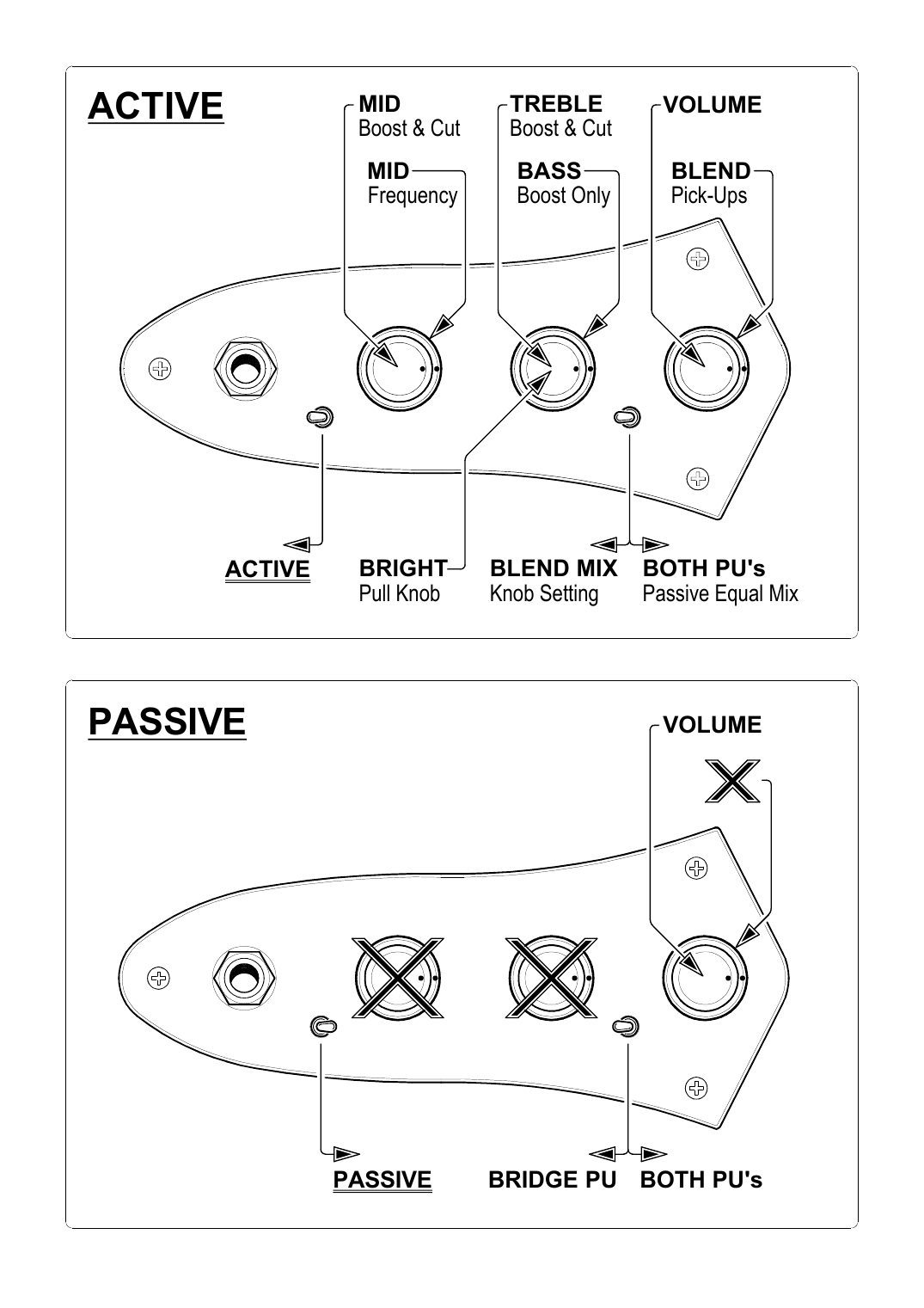
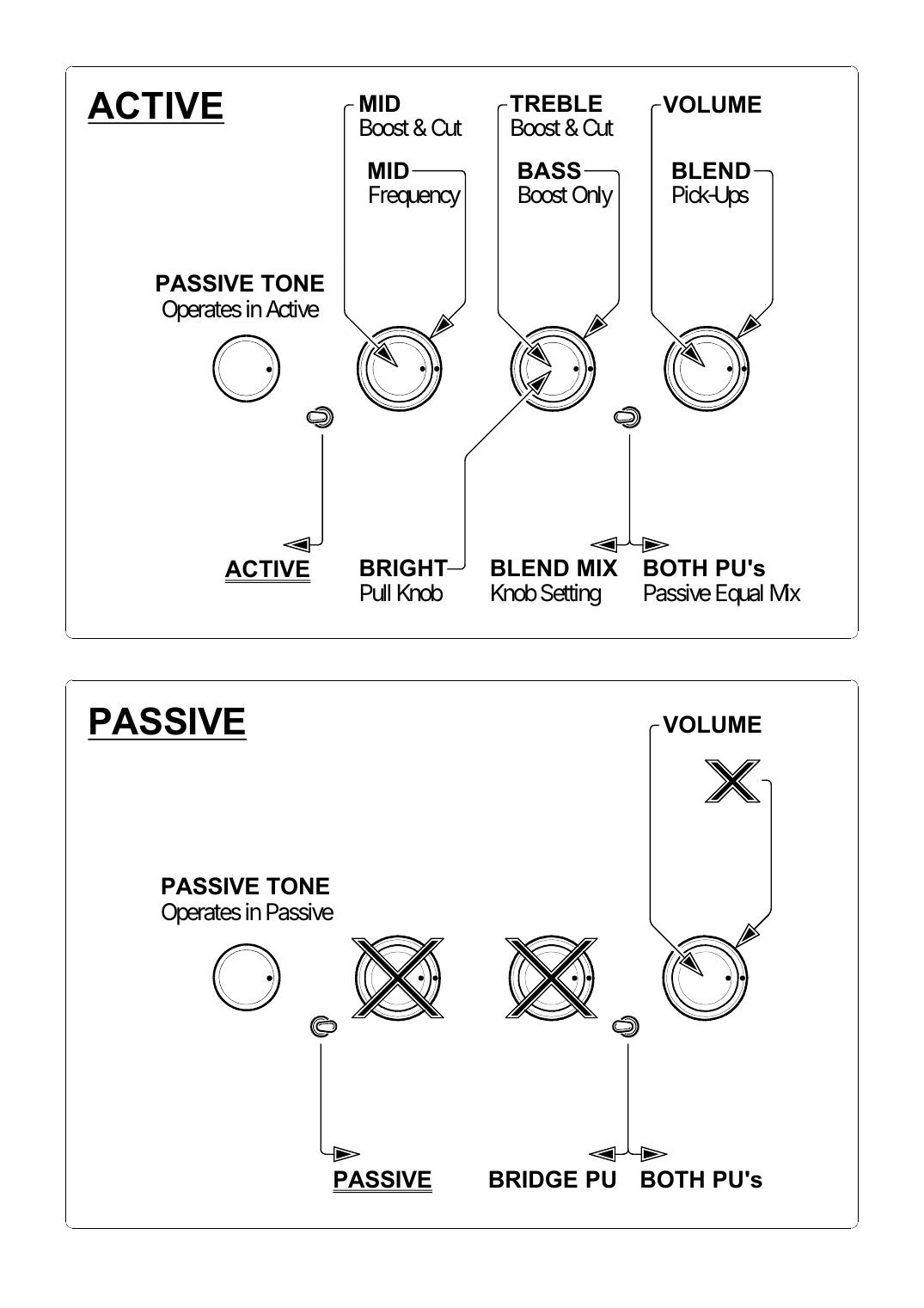
A drop-in replacement control plate for a standard Jazz Bass, with room for the PP3 battery. Three stacked knobs give an active blend, volume and 3-band EQ (bass, sweepable mid, treble with bright). Two mini switches add a passive equal mix of both pickups and a 'get-you-out-of-trouble' passive mode if the battery dies.
| Volume (upper knob, stack nearest the neck) | Active volume, low-impedance output |
|---|---|
| Blend (lower ring) | CW neck only, ACW bridge only, centre indent equal mix, with level compensation |
| Treble (upper knob, middle stack) | +12 dB @ 3 kHz boost, −12 dB @ 1 kHz cut; centre indent flat |
| Bright (pull treble knob) | +8 dB @ 7 kHz |
| Bass (lower ring, middle stack) | Boost only, +15 dB @ 50 Hz; indent midway |
| Mid (upper knob, stack nearest the jack) | ±12 dB; centre indent flat |
| Mid frequency (lower ring) | 150 Hz-3 kHz, continuously variable |
| Pickups switch (by the blend) | Active: toward the jack = blend knob works, away = both pickups, passive equal mix. Passive: toward the jack = bridge only, away = both |
| Active/passive switch (by the jack) | Toward the jack = active, away = passive (volume still works; EQ and blend off) |
| Power | PP3 9 V battery, switched on by plugging in a mono jack |
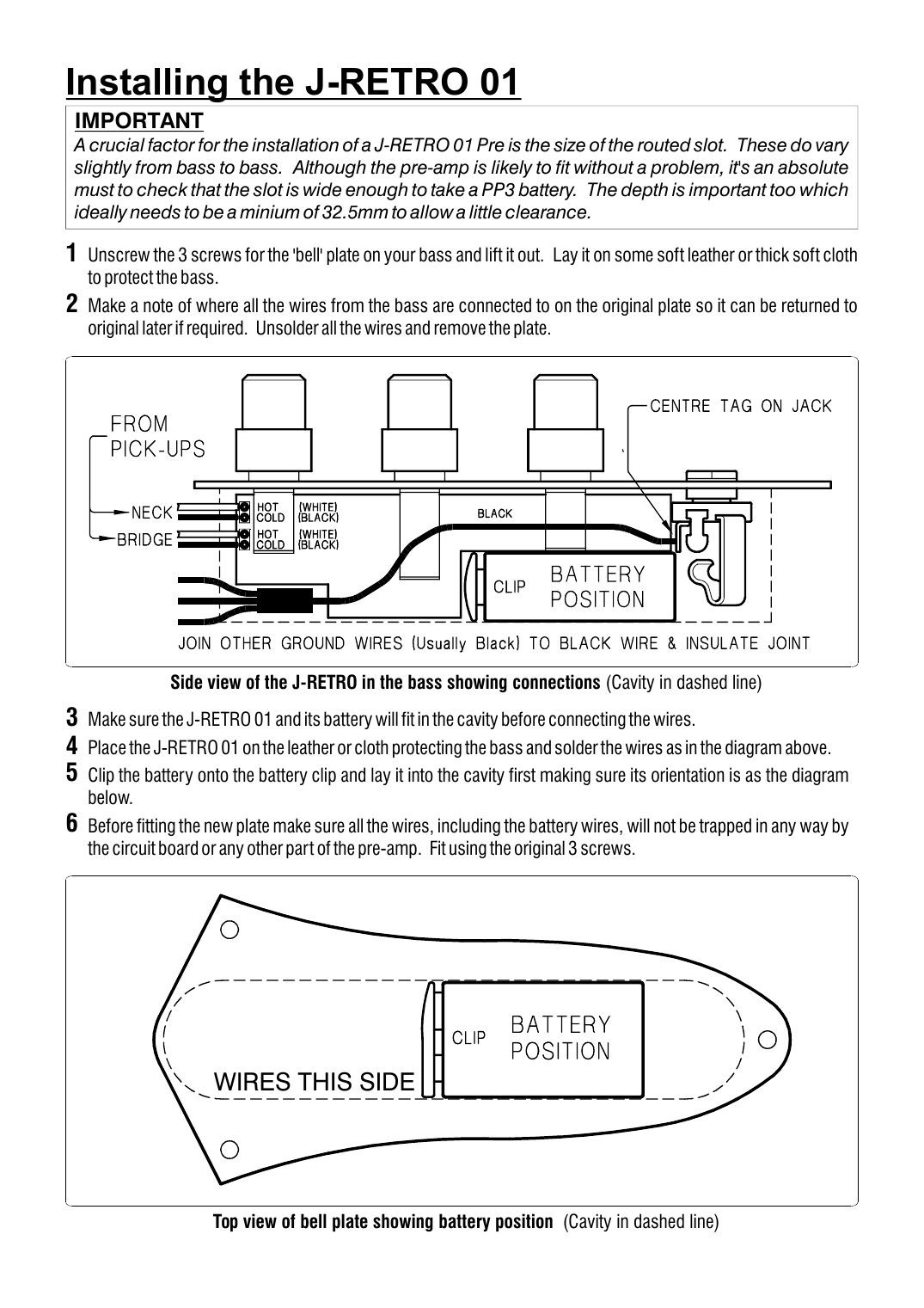
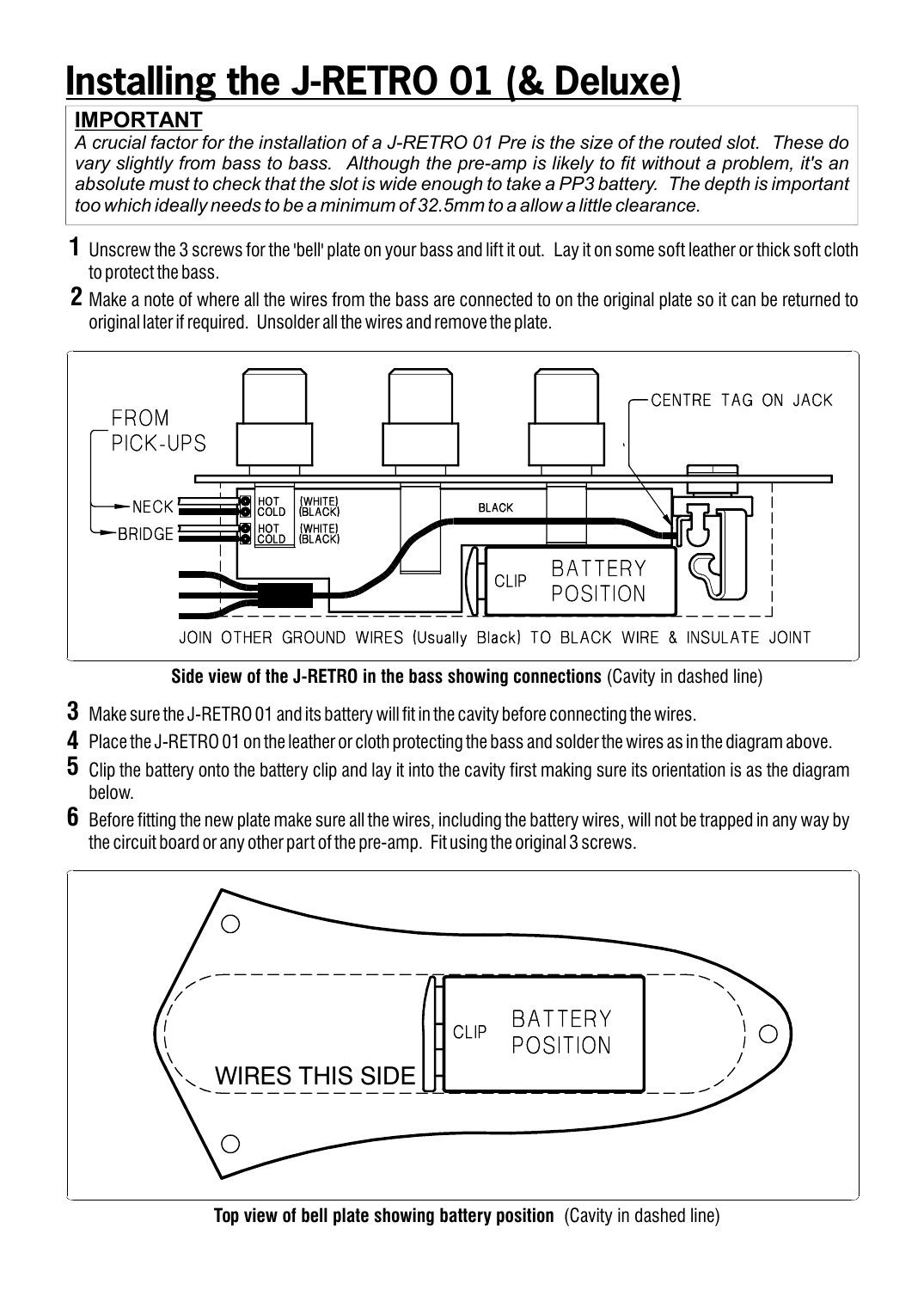
- Install: unscrew the 3 control-plate screws, note the old wiring, unsolder and lift it out; check the cavity is wide enough for a PP3 battery and ideally 32.5 mm deep.
- Lay the battery in the cavity first, oriented as John East shows, with the wires on the side he marks, then refit the plate with the original 3 screws.
Wire it with
J-Retro 01 Deluxe (J-Retro with passive tone)
The J-Retro 01 for Jazz Deluxe-style basses: the same active blend, volume and 3-band EQ, plus a fourth single knob that is a passive tone. Because the pickups stay separate until the active blend, the tone is a dual pot, one section per pickup, and it works in active and passive.
| Volume (upper knob, stack nearest the neck) | Active volume, low-impedance output |
|---|---|
| Blend (lower ring) | CW neck only, ACW bridge only, centre indent equal mix, with level compensation |
| Treble (upper knob, middle stack) | +12 dB @ 3 kHz boost, −12 dB @ 1 kHz cut; centre indent flat |
| Bright (pull treble knob) | +8 dB @ 7 kHz |
| Bass (lower ring, middle stack) | Boost only, +15 dB @ 50 Hz; indent midway |
| Mid (upper knob, stack nearest the jack) | ±12 dB; centre indent flat |
| Mid frequency (lower ring) | 150 Hz-3 kHz, continuously variable |
| Pickups switch (by the blend) | Active: toward the jack = blend knob works, away = both pickups, passive equal mix. Passive: toward the jack = bridge only, away = both |
| Active/passive switch (by the jack) | Toward the jack = active, away = passive (volume still works; EQ and blend off) |
| Passive tone (single knob) | Dual pot: a separate passive tone for each pickup, working in active and passive |
| Power | PP3 9 V battery, switched on by plugging in a mono jack |
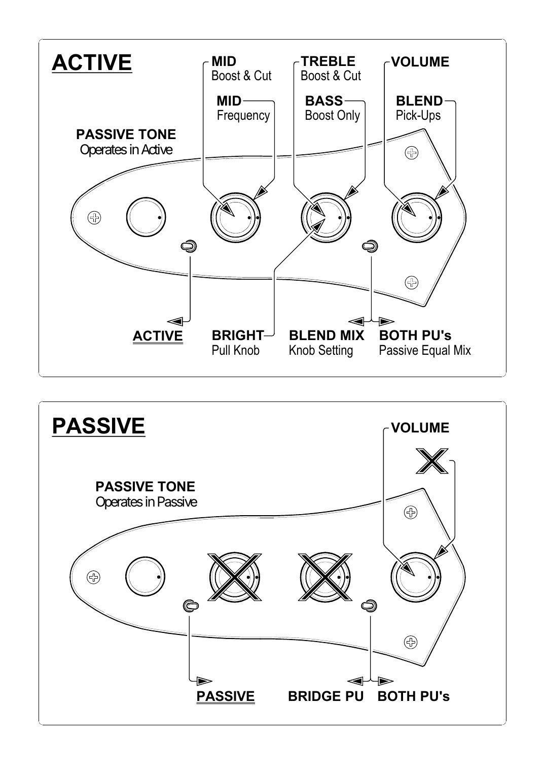
- The passive tone sits where a standard J plate has its jack; the Deluxe body has the jack elsewhere.
- Same cavity check as the J-Retro: room for the PP3 and ideally 32.5 mm depth.
Wire it with
DJ-Retro 01 for the Lakland Daryl Jones bass
The J-Retro 01 made to drop into the Lakland Daryl Jones signature bass without modification, battery included. Controls, switches and wiring are the same as the J-Retro 01.
| Volume (upper knob, stack nearest the neck) | Active volume, low-impedance output |
|---|---|
| Blend (lower ring) | CW neck only, ACW bridge only, centre indent equal mix, with level compensation |
| Treble (upper knob, middle stack) | +12 dB @ 3 kHz boost, −12 dB @ 1 kHz cut; centre indent flat |
| Bright (pull treble knob) | +8 dB @ 7 kHz |
| Bass (lower ring, middle stack) | Boost only, +15 dB @ 50 Hz; indent midway |
| Mid (upper knob, stack nearest the jack) | ±12 dB; centre indent flat |
| Mid frequency (lower ring) | 150 Hz-3 kHz, continuously variable |
| Pickups switch (by the blend) | Active: toward the jack = blend knob works, away = both pickups, passive equal mix. Passive: toward the jack = bridge only, away = both |
| Active/passive switch (by the jack) | Toward the jack = active, away = passive (volume still works; EQ and blend off) |
| Power | PP3 9 V battery, switched on by plugging in a mono jack |
- Install exactly as the J-Retro 01: check the PP3 fits and the cavity depth before you solder.
Wire it with
Marcus Retro 01 for Marcus Miller signature J basses
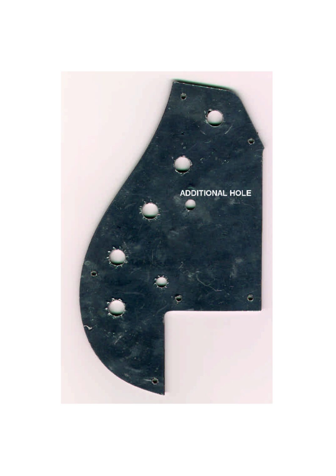
The J-Retro with passive tone, made to fit the Marcus Miller 4-string signature bass without modification. The version with a plate fits the 4-string only; the 'electronics only' version fits a Marcus V using the existing plate, which needs one extra hole for the pickups toggle.
| Volume (upper knob, stack nearest the neck) | Active volume, low-impedance output |
|---|---|
| Blend (lower ring) | CW neck only, ACW bridge only, centre indent equal mix, with level compensation |
| Treble (upper knob, middle stack) | +12 dB @ 1.5 kHz boost, −12 dB @ 1 kHz cut; centre indent flat |
| Bright (pull treble knob) | +8 dB @ 7 kHz |
| Bass (lower ring, middle stack) | Boost only, +15 dB @ 40 Hz; indent midway |
| Mid (upper knob, stack nearest the jack) | ±12 dB; centre indent flat |
| Mid frequency (lower ring) | 150 Hz-3 kHz, continuously variable |
| Pickups switch (by the blend) | Active: toward the jack = blend knob works, away = both pickups, passive equal mix. Passive: toward the jack = bridge only, away = both |
| Active/passive switch (by the jack) | Toward the jack = active, away = passive (volume still works; EQ and blend off) |
| Passive tone (single knob) | Dual pot: a separate passive tone for each pickup, working in active and passive |
| Power | PP3 9 V battery, switched on by plugging in a mono jack |
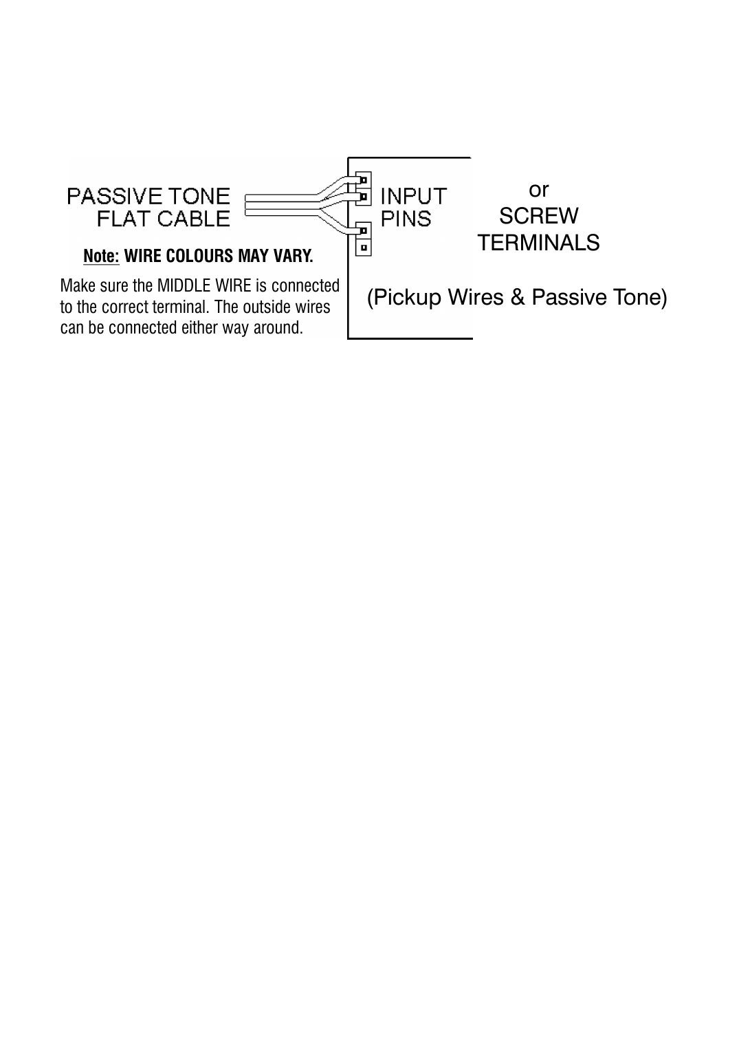
- Passive tone flat cable: it plugs onto the input pins (or screw terminals) with the pickup wires. Wire colours vary; make sure the MIDDLE wire goes to the correct terminal. The two outside wires can go either way round.
- Marcus V: drill the one additional hole for the pickups toggle where John East shows it.
Wire it with
Universal preamps
U-Retro 01 universal dual-input preamp
The J-Retro 01 circuit for any two-pickup bass, not just a J plate: three stacked knobs with an active blend, volume and 3-band EQ, a pickups switch and an active/passive switch. Two 0-12 dB presets set the gain of each pickup input.
| Volume (upper knob, stack nearest the neck) | Active volume, low-impedance output |
|---|---|
| Blend (lower ring) | CW neck only, ACW bridge only, centre indent equal mix, with level compensation |
| Treble (upper knob, middle stack) | +12 dB @ 3 kHz boost, −12 dB @ 1 kHz cut; centre indent flat |
| Bright (pull treble knob) | +8 dB @ 7 kHz |
| Bass (lower ring, middle stack) | Boost only, +15 dB @ 50 Hz; indent midway |
| Mid (upper knob, stack nearest the jack) | ±12 dB; centre indent flat |
| Mid frequency (lower ring) | 150 Hz-3 kHz, continuously variable |
| Pickups switch (by the blend) | Active: toward the jack = blend knob works, away = both pickups, passive equal mix. Passive: toward the jack = bridge only, away = both |
| Active/passive switch (by the jack) | Toward the jack = active, away = passive (volume still works; EQ and blend off) |
| Power | PP3 9 V battery, switched on by plugging in a mono jack |
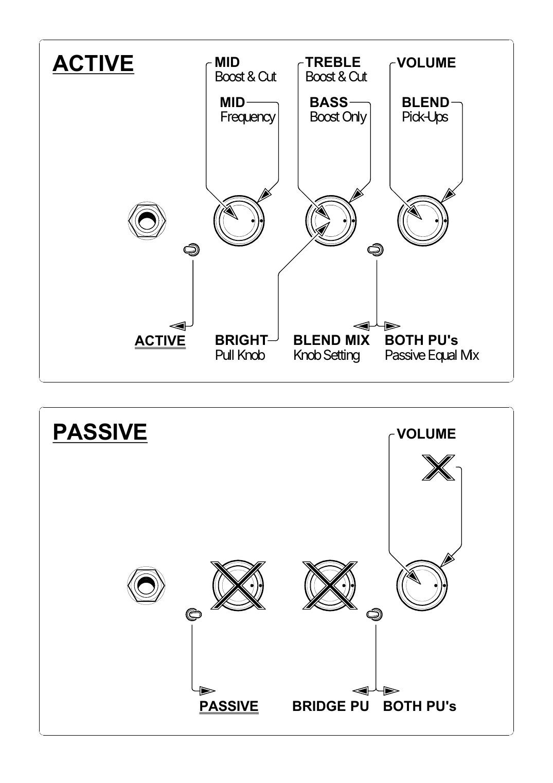
- Lay out the three stacks, the two mini switches and the jack to suit your cavity; the wiring is the same as the J-Retro.
Wire it with
U-Retro 01 Deluxe (U-Retro with passive tone)
The U-Retro 01 plus a single-knob passive tone (a dual pot, one section per pickup) that works in active and passive.
| Volume (upper knob, stack nearest the neck) | Active volume, low-impedance output |
|---|---|
| Blend (lower ring) | CW neck only, ACW bridge only, centre indent equal mix, with level compensation |
| Treble (upper knob, middle stack) | +12 dB @ 3 kHz boost, −12 dB @ 1 kHz cut; centre indent flat |
| Bright (pull treble knob) | +8 dB @ 7 kHz |
| Bass (lower ring, middle stack) | Boost only, +15 dB @ 50 Hz; indent midway |
| Mid (upper knob, stack nearest the jack) | ±12 dB; centre indent flat |
| Mid frequency (lower ring) | 150 Hz-3 kHz, continuously variable |
| Pickups switch (by the blend) | Active: toward the jack = blend knob works, away = both pickups, passive equal mix. Passive: toward the jack = bridge only, away = both |
| Active/passive switch (by the jack) | Toward the jack = active, away = passive (volume still works; EQ and blend off) |
| Passive tone (single knob) | Dual pot: a separate passive tone for each pickup, working in active and passive |
| Power | PP3 9 V battery, switched on by plugging in a mono jack |
- The passive tone's flat cable connects with the pickup wires: get the middle wire on the right terminal (see the Marcus Retro 01 note).
Wire it with
U-Retro 5-Knob Deluxe (passive blend, separate knobs)
Based on the J-Retro 01 but laid out as three single knobs and two stacks for rear-mounting in the body (10 mm threaded bushes, flat-wire connections). Unlike the other Retros it uses a passive blend, then a passive tone with a push/pull active/passive switch, then the preamp.
| Volume (single knob) | Two sections: one for the passive path, one for the active path; 0-12 dB input-gain preset |
|---|---|
| Blend (single knob) | Passive blend, works in both modes: CW neck, ACW bridge, centre indent equal mix |
| Treble / Bright (stack, upper) | +12 dB @ 3 kHz, −12 dB @ 1 kHz; pull for Bright +8 dB @ 7 kHz |
| Bass (stack, lower) | Boost only, +15 dB @ 50 Hz |
| Mid / frequency (stack) | ±12 dB, 150 Hz-3 kHz |
| Passive tone + push/pull | Tone works in both modes; knob down = active, pulled up = passive |
| Power | 9 V battery, switched by plugging in a mono jack |
| # | Wire | Goes to |
|---|---|---|
| 1 | Neck pickup hot / cold | Blend pot screw terminals, NECK HOT and COLD (top pair, viewed from the top) |
| 2 | Bridge pickup cold / hot | Blend pot screw terminals, BRIDGE COLD and HOT (bottom pair: note cold is above hot here) |
| 3 | Passive tone lead: white wires | Board HOT input (the tone lead runs from the blend to the board) |
| 4 | Passive tone lead: black wires | Board COLD input |
| 5 | Battery red | Board +VE |
| 6 | Battery black | Output jack ring |
| 7 | Board OUTPUT | Output jack tip |
| 8 | Board 0V/GROUND | Output jack sleeve |
| 9 | Copper screening foil | Wire soldered from the foil to the 0V/ground pin of the jack |
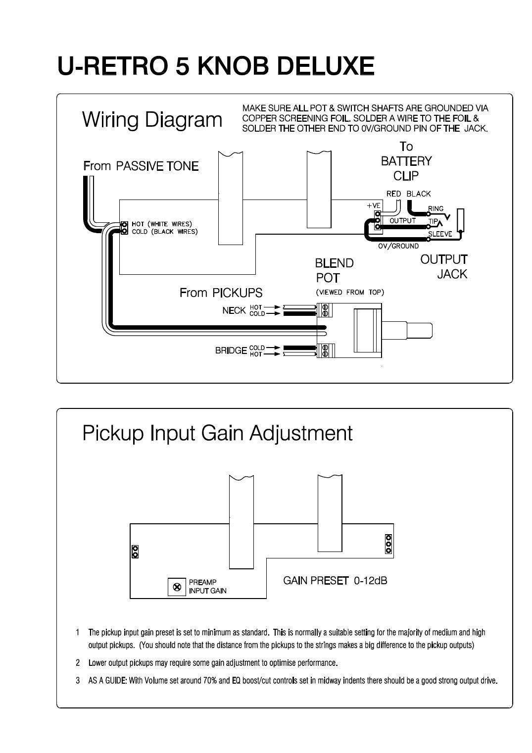
- Active path: pickups → passive blend → passive tone → preamp input → EQ and volume → low-impedance output to the jack. Passive path: blend → tone → the passive volume section → jack.
- One 0-12 dB preamp input-gain preset (set to minimum from the factory).
Wire it with
Uni-Pre universal active/passive preamp system (3, 4 or 5 knobs)
A modular preamp for any bass with rear-cavity electronics, in 3-, 4- or 5-knob layouts with 2- or 3-band EQ. Custom dual pots run two completely separate paths, active and passive, from one set of knobs, so the blend is smooth in active and still works in passive. Modules plug together; pickups, power and ground go on screw terminals.
| Volume | Sets both the active and passive output |
|---|---|
| Blend | Both paths: ACW bridge alone, CW neck alone, centre click equal mix. Gain trims 0-12 dB per pickup (active) |
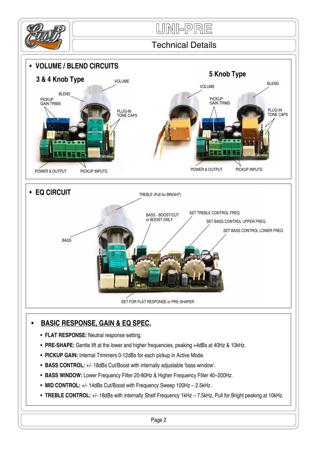
| Bass | ±18 dB (or boost only, by jumper), centre click; 'bass window' set inside: lower 20-80 Hz, upper 40-200 Hz |
| Treble (pull for Bright) | ±18 dB shelf, frequency set inside 1-7.5 kHz; Bright peaks at 10 kHz |
| Mid + frequency | ±14 dB, sweep 100 Hz-2.5 kHz, centre click |
| Active/passive | 3-knob: mini toggle. 4- and 5-knob: push/pull on the passive tone (pull = passive) |
| Passive tone (4- and 5-knob) | CW no effect, ACW darker; plug-in tone caps per pickup |
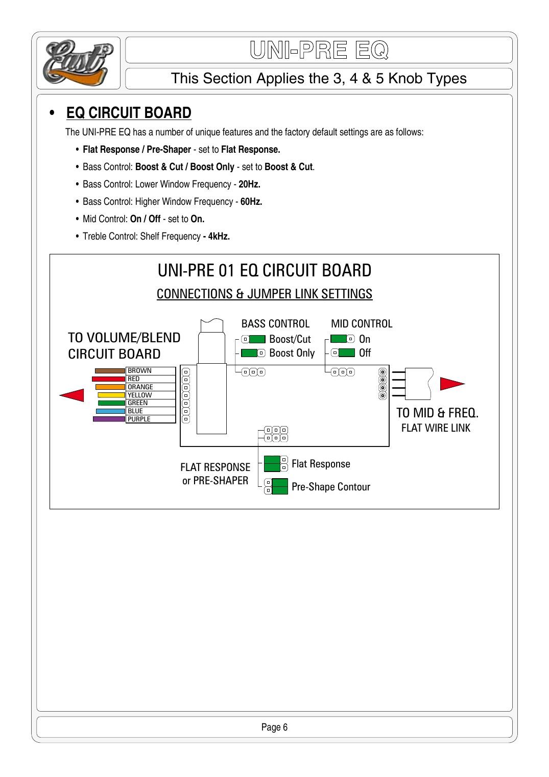
| Response jumper | Flat, or Pre-Shape (+4 dB at 40 Hz and 10 kHz) |
| Power | 9 V battery, on when a mono jack is plugged in |
| # | Setting | Factory |
|---|---|---|
| 1 | Flat response / Pre-Shaper | Flat response |
| 2 | Bass: boost & cut / boost only | Boost & cut |
| 3 | Bass window lower frequency | 20 Hz |
| 4 | Bass window upper frequency | 60 Hz |
| 5 | Mid control on / off | On |
| 6 | Treble shelf frequency | 4 kHz |
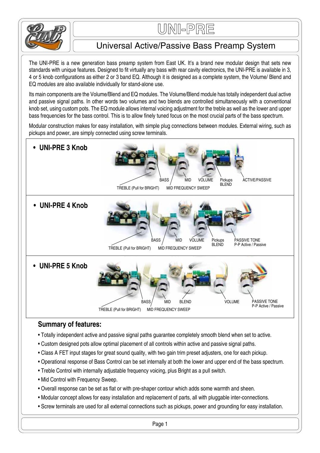
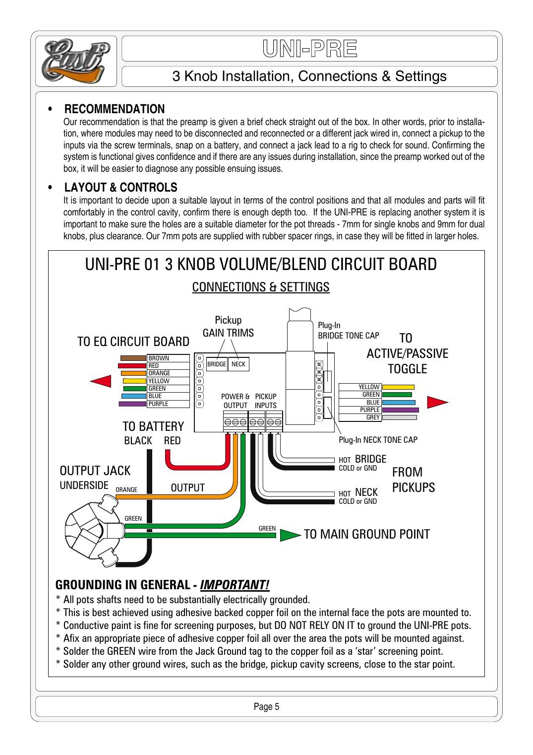
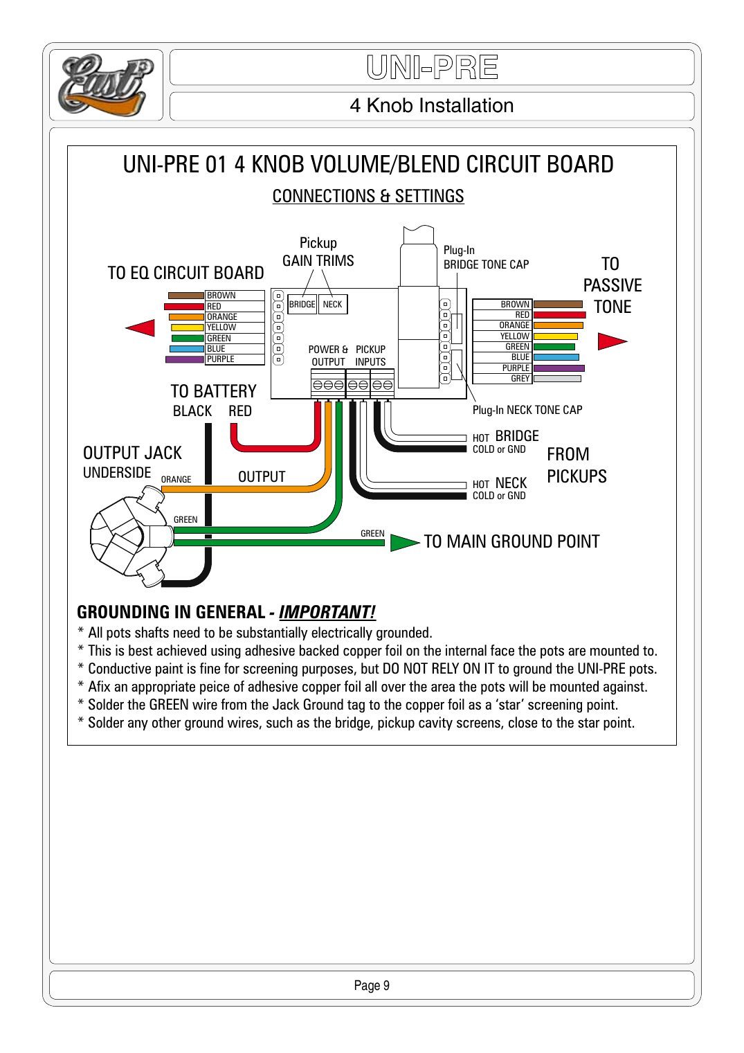
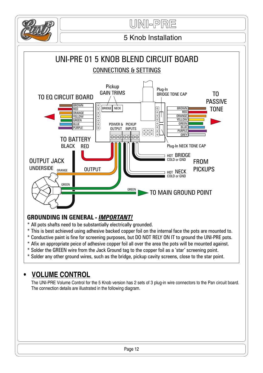
- The 3-knob version has an active/passive mini toggle on the board's 5-way lead; the 4- and 5-knob versions put that lead on the passive tone push/pull.
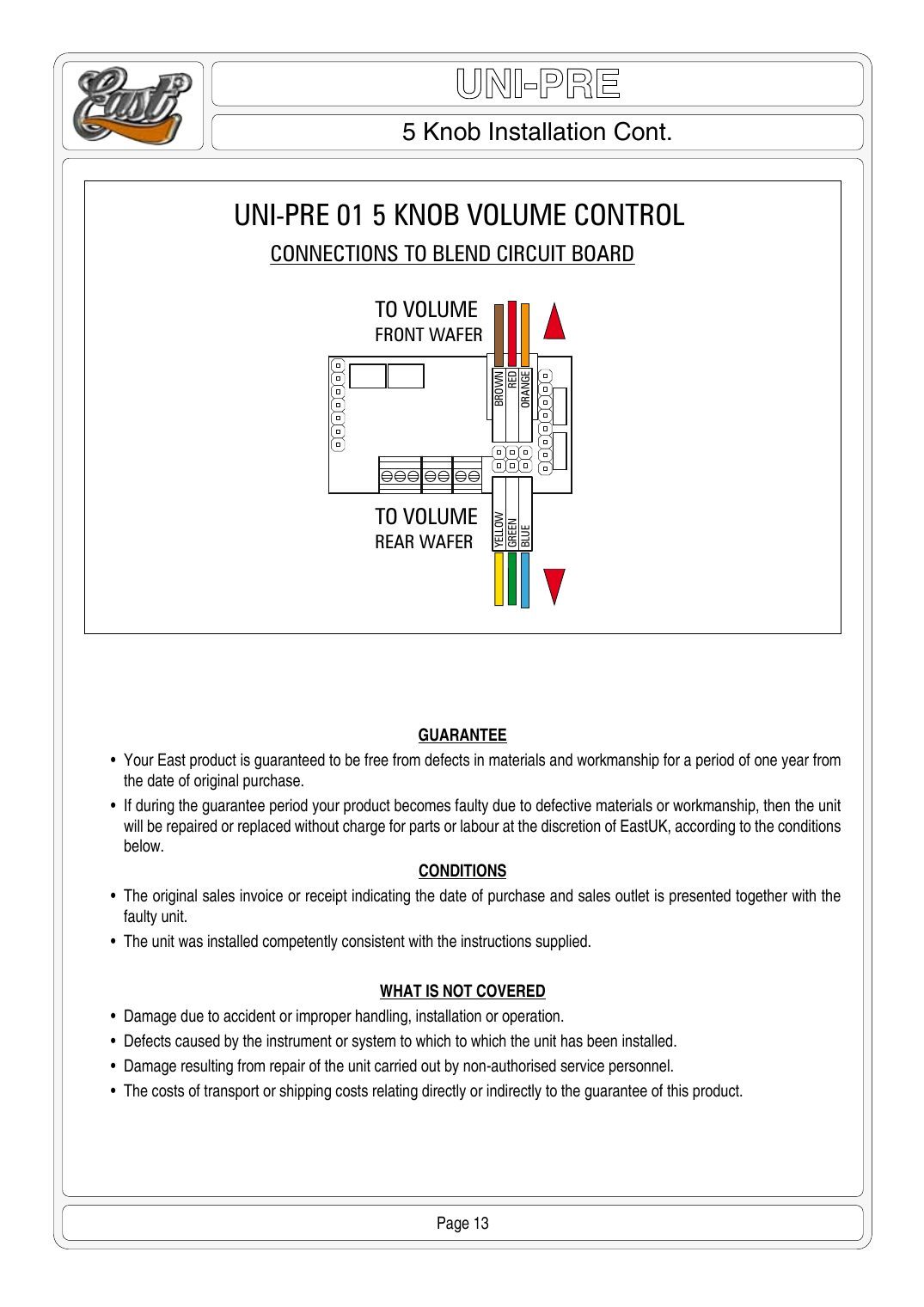
- 5-knob: the volume is a separate pot with two 3-wire plugs: brown, red, orange to the front wafer, yellow, green, blue to the rear wafer.
- FUNCTION-LEVEL for the jumpers: the page lists what each one does; follow John East's drawing for the jumper positions.
Wire it with
P-style retro-fit
P-Retro active/passive retro-fit for P-style basses
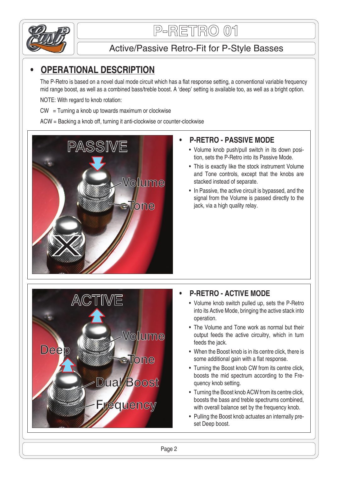
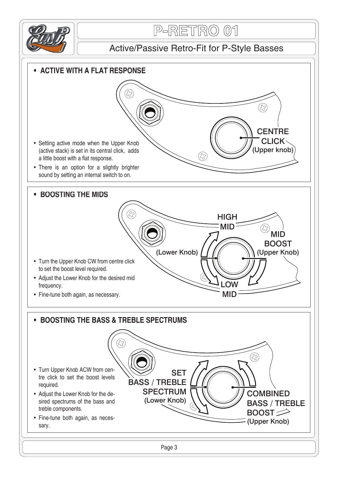
Turns a P-Bass volume and tone into two stacked knobs, each with a pull switch, without modifying the bass. The Volume/Tone stack works exactly like the stock controls; pull the volume for active (class A FET input, +2.5 dB, flat), and the second stack gives a mid boost or a combined bass/treble boost, plus a Deep boost. A relay gives a true passive bypass and the internal Li-Pol battery is recharged through the jack.
| Volume (upper knob, Volume/Tone stack) | Pushed down = passive (relay bypass, like a stock P). Pulled up = active |
|---|---|
| Passive tone (lower knob) | Works in both modes; plug-in cap, 0.1 µF fitted, 0.047 µF included |
| Dual boost (upper knob, Active stack) | Centre click: +2.5 dB flat. CW: mid boost 0-15 dB. ACW: combined bass/treble boost |
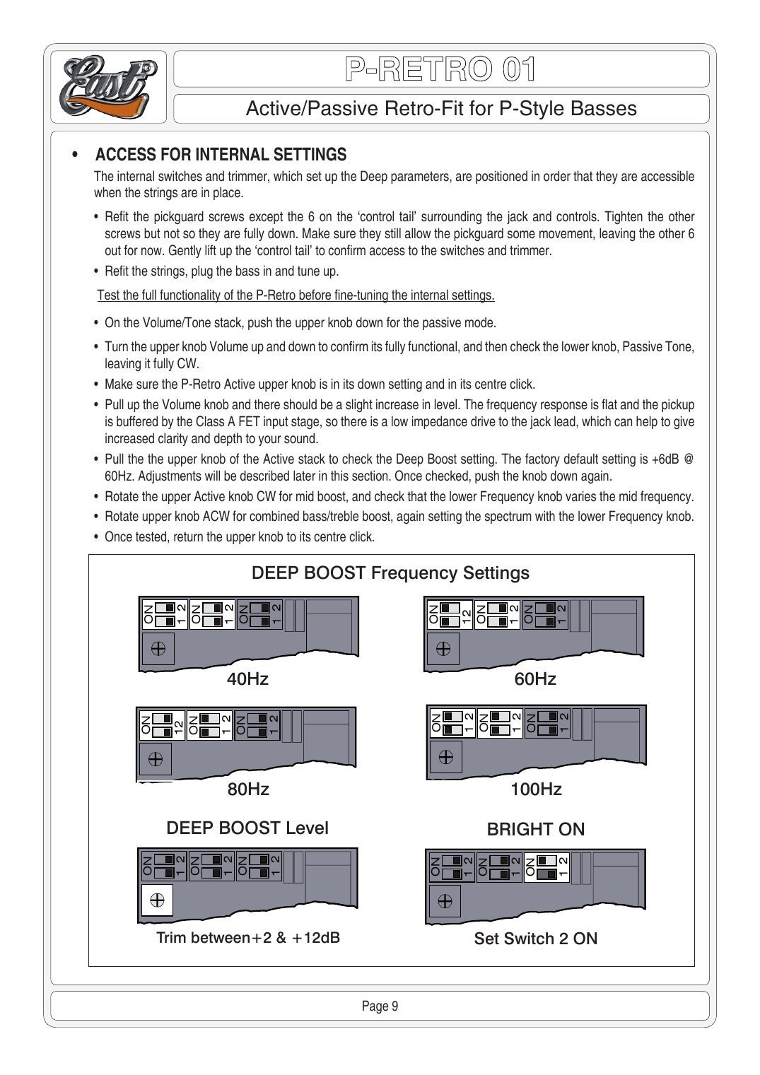
| Deep (pull the boost knob) | Deep boost at 40, 60, 80 or 100 Hz (internal switches), level +2 to +12 dB (trimmer). Factory: +6 dB @ 60 Hz |
| Frequency (lower knob, Active stack) | 250 Hz-2 kHz, 41 click positions |
| Bright (internal switch) | Switch 2 ON: brighter active sound |
| Battery | Internal Li-Pol, up to 40 hours per charge, about 4 hours from empty; auto passive if it runs low |
| Charge LED | Red charging, green done; fit in the supplied bezel (6 mm hole) or leave it in the cavity |
- Charging: plug the special jack charger adaptor into the bass first, then the charger lead into the adaptor, then the charger into the mains. Switch off at the mains before unplugging.
- The Deep switches and level trimmer can be reached with the strings on: leave out the 6 pickguard screws around the control tail and ease it up.
- FUNCTION-LEVEL for the Deep frequency switches: the drawing shows the switch positions for 40, 60, 80 and 100 Hz; follow it.
Wire it with
Stingray-style MMSR preamps
MMSR 3-knob 2-band (Stingray-style) preamp
A 2-band EQ voiced like the original Music Man Stingray, on a modern dual op-amp (not a copy of the circuit). Like the original it is not flat with the knobs at halfway. Three single knobs: volume, bass, treble.
| Treble | +20 dB / −16 dB @ 10 kHz: more boost than cut, the Stingray 'sizzle' |
|---|---|
| Bass | +14 dB / −7 dB @ 40 Hz; boost keeps rising toward the low end, cut is a shelf |
| Volume | Pickup feeds the preamp directly, like the original |
| Power | 9-18 V DC; battery clip supplied |
- Pots are marked V (volume), B (bass), T (treble), with 7 mm threads; leave the rubber spacers in if the holes are the original larger size.
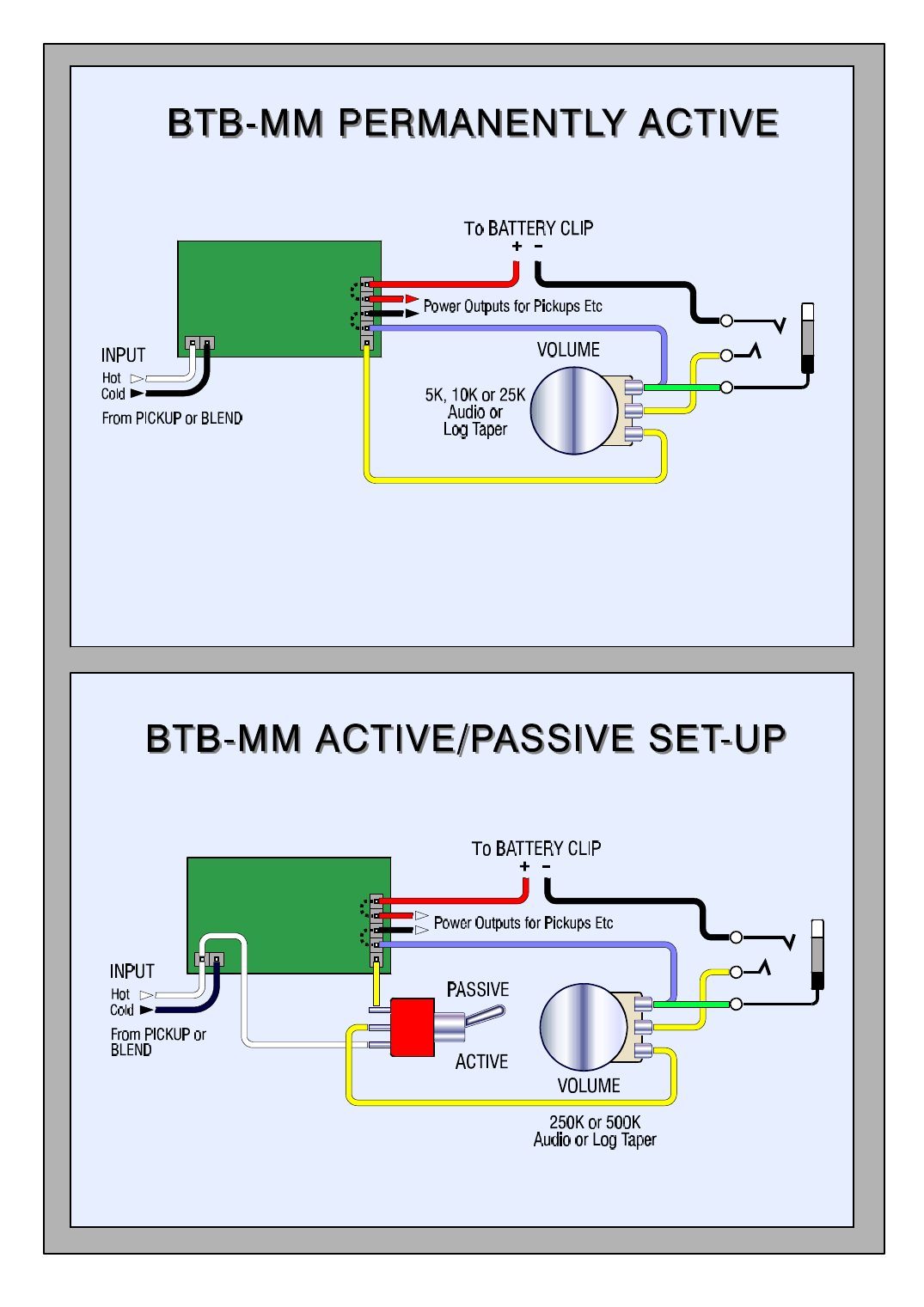
- Mount the preamp on the back of the bass and treble pots with its foam tape, and wire the pickup to the BTB-MM board's input pins.
- Most basses have a battery box: cut off the supplied clip and join red to red, black to black, under the heat-shrink sleeves threaded on the black ground wire.
- Connect the jack's black ground wire to the bass's other grounds, such as the bridge.
Wire it with
MMSR 3-knob 3-band (Stingray-style) preamp with mid sweep
The MMSR 2-band EQ with bass and treble stacked on one knob, so a Mid Sweep 01 stack fits on a standard 3-knob plate. The volume sits between the bass/treble section and the mid, so the mid drives the jack with a low-impedance output.
| Volume (single knob) | Level from the bass/treble section into the mid section |
|---|---|
| Treble (stack, upper) | +20 dB / −16 dB @ 10 kHz; pull for Bright +5 dB @ 7 kHz |
| Bass (stack, lower ring) | +14 dB / −7 dB @ 40 Hz |
| Mid (stack, upper) | ±12 dB, centre indent flat |
| Mid frequency (lower ring) | 100 Hz-1 kHz (both DIL switches ON) or 200 Hz-2 kHz (both OFF) |
| Power | 9-18 V DC |
- Plate positions: volume in the volume hole, the bass/treble board (two bare input pins at one end) in the old treble hole, the mid sweep stack in the old bass hole, the pre-wired jack in the jack hole.
- Wire the pickup to the bass/treble board's input pins as on the BTB-MM drawing; battery and ground as for the 2-band.
- FUNCTION-LEVEL: the links between the bass/treble board, the volume and the mid sweep come pre-wired and aren't drawn.
Wire it with
MMSR 4-knob 3-band (Stingray-style) preamp with mid sweep
The MMSR 2-band EQ on separate volume, bass and treble pots, plus a Mid Sweep 01 stack in the old mid hole, for 4-knob Stingray-style plates.
| Treble | +20 dB / −16 dB @ 10 kHz: more boost than cut, the Stingray 'sizzle' |
|---|---|
| Bass | +14 dB / −7 dB @ 40 Hz; boost keeps rising toward the low end, cut is a shelf |
| Mid (stack, upper) | ±12 dB, centre indent flat |
| Mid frequency (lower ring) | 100 Hz-1 kHz (both DIL switches ON) or 200 Hz-2 kHz (both OFF) |
| Volume | Pickup feeds the preamp directly, like the original |
| Power | 9-18 V DC; battery clip supplied |
- Pots are marked V, B and T (7 mm threads). The bass/treble board can float, or stick it (foam pads) to a surface such as the back of the mid sweep board.
- Mount the mid sweep stack in the old mid pot hole. Fit the pre-wired jack on its plate, or move its wires to the original jack in the same order.
- FUNCTION-LEVEL: the links between the boards come pre-wired and aren't drawn.
Wire it with
Modules and buffers
BTB-01 bass/treble/bright stack
The middle stack of the J-Retro 01 on its own: one dual concentric knob with treble (pull for bright) and boost-only bass. Use it permanently active or with an active/passive switch.
| Treble (upper knob) | +12 dB @ 3 kHz, −12 dB @ 1 kHz; centre indent flat |
|---|---|
| Bright (pull treble) | +8 dB @ 7 kHz |
| Bass (lower ring) | Boost only, +15 dB @ 50 Hz; indent midway |
| Power | 9-18 V DC |
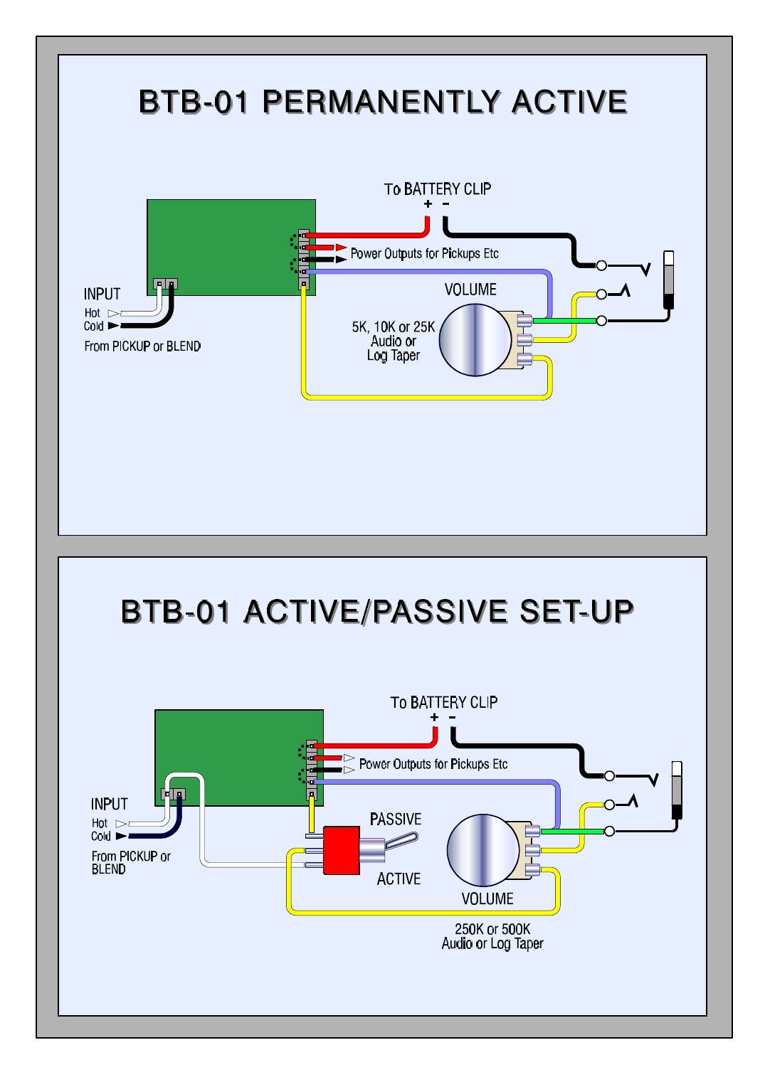
- Its input can come from one pickup or from a blend pot.
Wire it with
BTBM-01 bass/treble stack with two-input mixer
The BTB bass/treble/bright stack plus a separate low-noise, unity-gain two-input mixer, for example to mix a piezo preamp with a magnetic pickup circuit.
| Treble (upper knob) | +12 dB @ 3 kHz, −12 dB @ 1 kHz; pull for Bright +8 dB @ 7 kHz |
|---|---|
| Bass (lower ring) | Boost only, +15 dB @ 50 Hz |
| Mixer | Two inputs, unity gain, low-impedance output |
| Power | 9-18 V DC |
| # | Pin | Goes to |
|---|---|---|
| 1 | +9-18 Volts (2 linked pins) | Battery + |
| 2 | 0 Volts/GROUND (2 linked pins) | Ground / battery − |
| 3 | INPUT TO EQ: Hot, Cold | Pickup or blend output |
| 4 | EQ OUTPUT: Hot, Cold | A mixer input (Hot only), or onward |
| 5 | MIXER INPUTS: Hot, Cold (×2) | The signals to mix, e.g. EQ output and a piezo preamp |
| 6 | MIXER OUTPUT: Hot, Cold | Volume or output jack |
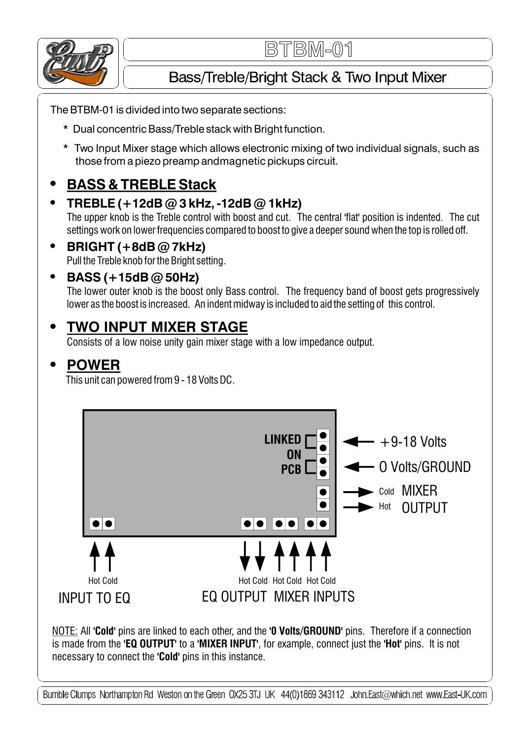
- To run the EQ into the mixer, link just the EQ OUTPUT Hot to a MIXER INPUT Hot: the Cold pins are already common.
Wire it with
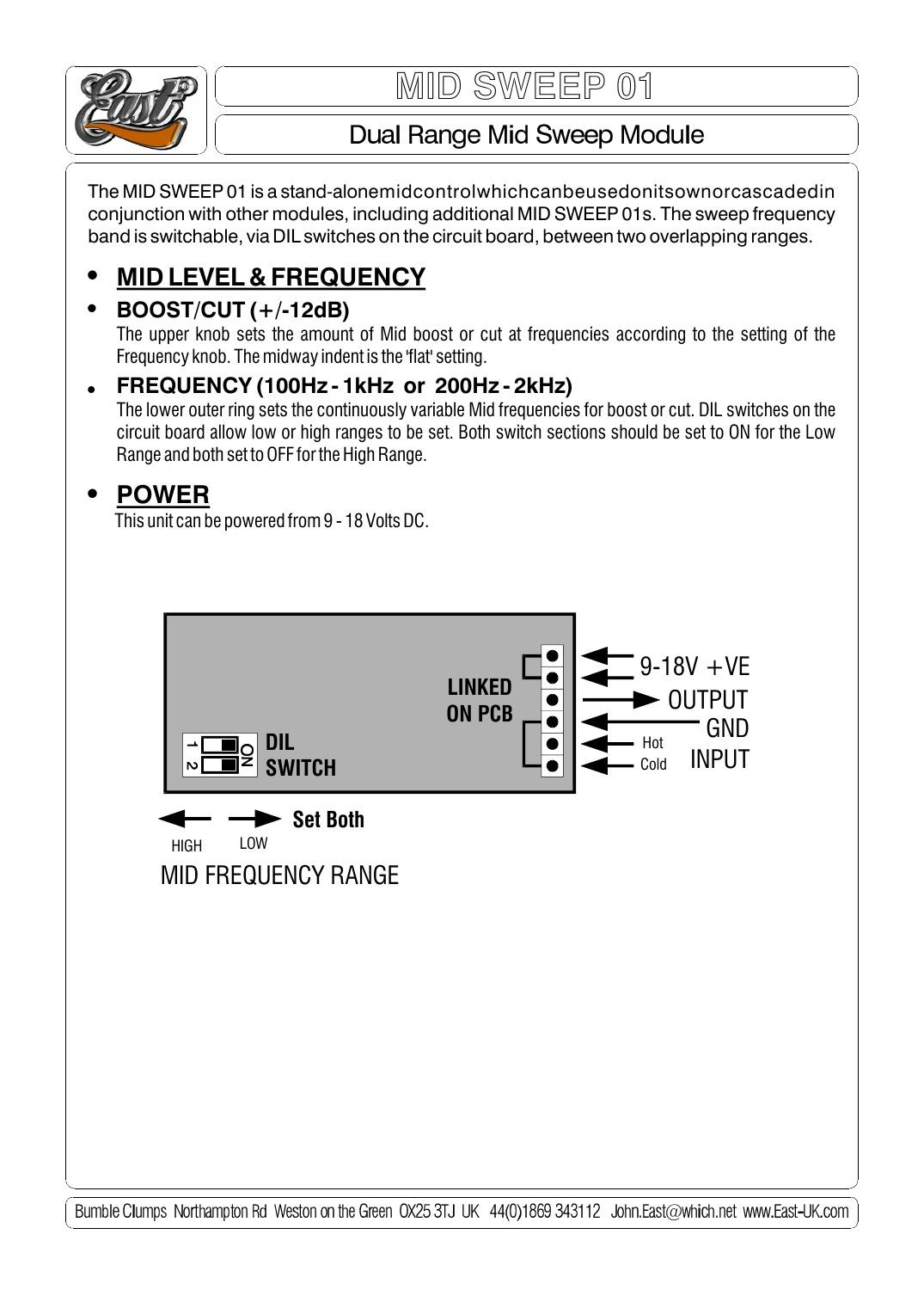
Mid Sweep 01 dual-range mid module
A stand-alone mid control on one dual concentric stack. Use it on its own or after other modules, including more Mid Sweep 01s.
| Boost/cut (upper knob) | ±12 dB; centre indent flat |
|---|---|
| Frequency (lower ring) | 100 Hz-1 kHz (both DIL switches ON) or 200 Hz-2 kHz (both OFF) |
| Power | 9-18 V DC |
| # | Pin | Goes to |
|---|---|---|
| 1 | 9-18 V +VE (2 linked pins) | Battery +, or on to the next module |
| 2 | OUTPUT | Volume, next module or jack tip |
| 3 | GND | Ground |
| 4 | INPUT Hot | Signal in |
| 5 | INPUT Cold | Signal ground (linked to GND on the board) |
- Set both DIL switch sections the same: both ON for the low range, both OFF for the high range.
Wire it with
MPB-01 piezo preamp and four-input mixer
A high-input-impedance piezo input stage (gain preset 0-12 dB, optional tone pot) plus a separate unity-gain mixer for up to four signals, such as the piezo pre and magnetic pickup circuits.
| Piezo gain preset | Unity to +12 dB |
|---|---|
| Optional tone pot | 250K log: high-frequency roll-off for the piezo signal (not on the piezo input itself) |
| Mixer | Up to four inputs, unity gain, low-impedance output |
| Power | 9-18 V DC |
| # | Pin | Goes to |
|---|---|---|
| 1 | PIEZO INPUT: Hot, Cold | Piezo pickup |
| 2 | OPTIONAL TONE CONTROL (2 pins) | 250K log pot |
| 3 | PIEZO PRE OUTPUT | A mixer input (Hot), or onward |
| 4 | GND (3 linked pins) | Ground / battery − |
| 5 | 9-18 V +VE | Battery + |
| 6 | MIXER INPUTS 1-4: Hot, Cold | Piezo pre output, magnetic pickup circuits |
| 7 | MIXER OUTPUT | Volume or output jack |
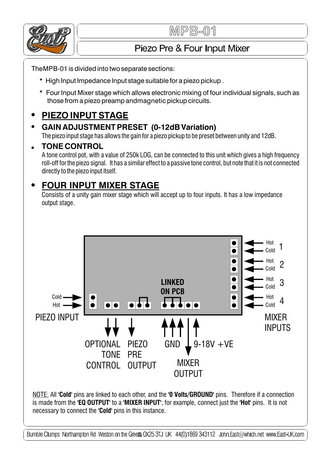
- Between modules connect only the Hot pins: all Cold pins are linked to ground. (John East's note says 'EQ OUTPUT'; on the MPB-01 that means the piezo pre output.)
Wire it with
The hookups
Retro 01 boards: pickups, battery and output jack, wire by wire
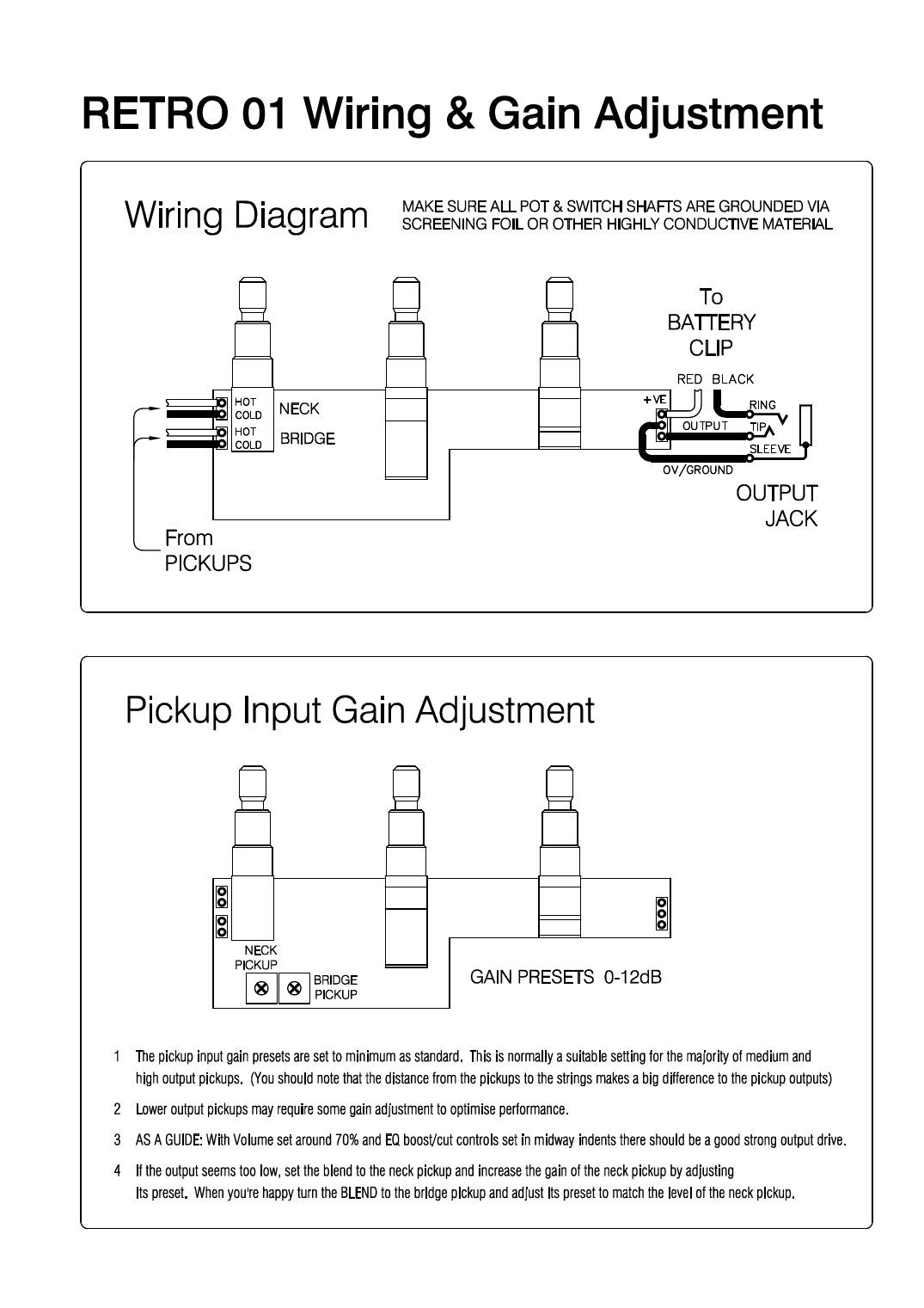
The J-Retro 01, J-Retro 01 Deluxe, DJ-Retro 01, Marcus Retro 01, U-Retro 01 and U-Retro 01 Deluxe all use the same 'RETRO 01 Wiring & Gain Adjustment' drawing. The preamp comes built on its control plate; you connect two pickups, the battery clip and the output jack.
You need: The Retro 01 preamp, a PP3 (9 V) battery, a stereo (TRS) output jack, two passive pickups, screening foil.
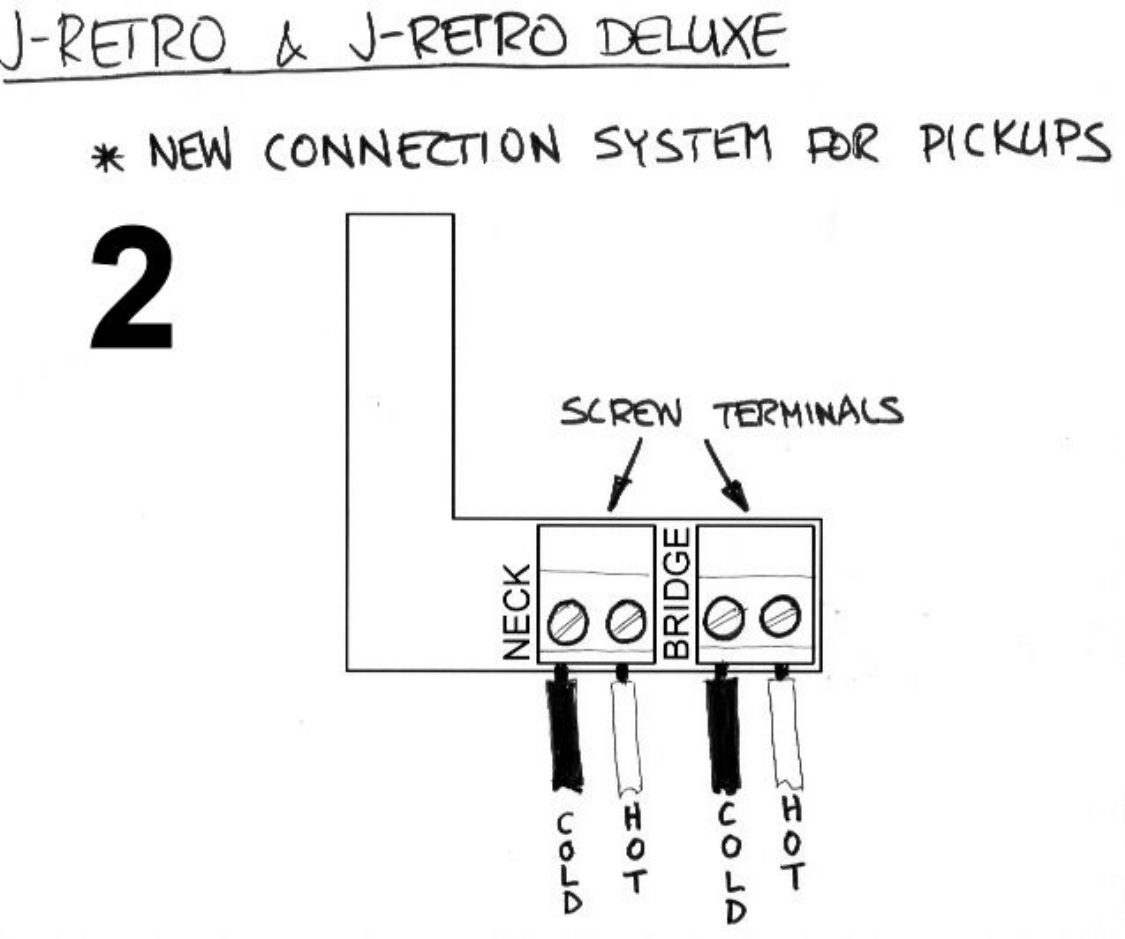
| # | From | To | Notes |
|---|---|---|---|
| 1 | Neck pickup: hot | Board terminal NECK HOT (by the volume/blend stack) | On later boards these are screw terminals (white = hot on John East's sketch) |
| 2 | Neck pickup: cold (ground) | Board terminal NECK COLD | Black on John East's sketch |
| 3 | Bridge pickup: hot | Board terminal BRIDGE HOT | |
| 4 | Bridge pickup: cold (ground) | Board terminal BRIDGE COLD | |
| 5 | Battery clip: red | Board pin +VE (jack end of the board) | Battery + |
| 6 | Battery clip: black | Output jack: RING | Battery −. A mono plug joins ring to sleeve, so plugging in turns the preamp on |
| 7 | Board pin OUTPUT | Output jack: TIP | Low-impedance active output (passive mode also comes out here) |
| 8 | Board pin 0V/GROUND | Output jack: SLEEVE | Ground |
| 9 | Screening foil in the cavity | Ground (jack sleeve) | John East: make sure all pot and switch shafts are grounded through screening foil |
Step by step
- Check the cavity first: the preamp and a PP3 battery must fit, and John East asks for at least 32.5 mm depth on J-style basses.
- Note where the old wires went, then unsolder them and lift out the old plate.
- Connect the neck pickup's hot and cold to the NECK terminals, and the bridge pickup's hot and cold to the BRIDGE terminals. Go by the HOT/COLD labels on the board.
- Connect the battery clip red to +VE, take the battery clip black to the jack's ring, the board OUTPUT to the jack tip and 0V/GROUND to the jack sleeve.
- Ground the pot and switch shafts through screening foil, clip on the battery, make sure no wire is trapped, and refit the plate with the original screws.
- Set the gain presets: they ship at minimum. If the output is low, turn the blend to the neck pickup and raise its preset, then match the bridge preset to it.
- Gain presets (0-12 dB, one per pickup): with volume around 70% and the EQ in its centre indents there should be a good strong output.
- The pickups switch must point toward the jack for the blend knob to work (see each model below).
- John East's later screw-terminal sketch lists the terminals COLD then HOT for each pickup, while the main drawing lists HOT above COLD: use the labels printed on your board.
BTB-01 and BTB-MM boards: permanently active or with an active/passive switch
The BTB-01 bass/treble stack and the BTB-MM board in the MMSR preamps share one drawing: a pickup (or a blend) into the board, the board into a volume pot, the volume into a stereo jack. The second version adds a DPDT mini toggle for passive.
You need: BTB-01 or BTB-MM board, volume pot (5K, 10K or 25K for permanently active; 250K or 500K with the active/passive switch), DPDT on-on mini toggle (active/passive version), stereo output jack, 9 V battery clip.
| # | From | To | Notes |
|---|---|---|---|
| 1 | Pickup (or blend output): hot | Board INPUT: Hot pin | The two bare pins at one end of the board |
| 2 | Pickup (or blend output): cold | Board INPUT: Cold pin | |
| 3 | Battery clip: red | Board + pin (top pin of the strip) | 9-18 V |
| 4 | Battery clip: black | Output jack: ring | Plugging a mono lead in completes the battery circuit |
| 5 | Board power outputs (+ and −) | Active pickups, if any | Optional: supply for active pickups |
| 6 | Board audio OUTPUT | Volume pot: outer lug (hot end) | Permanently active. With the switch, this goes to the toggle's ACTIVE side instead |
| 7 | Board 0 V / ground | Volume pot: other outer lug | Ground end |
| 8 | Volume pot: middle lug | Output jack: tip | Signal out |
| 9 | Volume pot: ground lug | Output jack: sleeve | Ground |
| 10 | Active/passive version: pickup hot | Toggle: PASSIVE side, as well as the board input | Passive feeds the pickup straight to the volume |
| 11 | Active/passive version: toggle common | Volume pot: outer lug (hot end) | Use a 250K or 500K volume in this version |
Step by step
- Solder the pickup (or blend) hot and cold to the board's INPUT pins.
- Connect the battery clip red to the board's + pin and the battery clip black to the stereo jack's ring.
- Permanently active: board OUTPUT to one outer lug of a 5K-25K volume, board ground to the other outer lug, volume middle lug to the jack tip, ground to the jack sleeve.
- Active/passive: run the board OUTPUT to one side of the toggle and the pickup hot to the other side, and the toggle common to the volume's hot lug. Use a 250K or 500K volume.
- If you have active pickups, power them from the board's power output pins. Test before closing up.
- Pot values: 5K, 10K or 25K audio or log for permanently active; 250K or 500K audio or log with the active/passive switch, so the pickup sees a normal load in passive.
- FUNCTION-LEVEL for the board's pin order: the drawing shows which coloured wire goes to which pin; follow it.
- The board runs on 9-18 V DC.
John East modules: power, ground, input and output pins (Mid Sweep 01, BTBM-01, MPB-01)
John East's add-on modules have labelled pin strips rather than wires. Each takes 9-18 V and ground, a hot/cold input and gives a low-impedance output. You can chain them: for example a piezo pre into a mixer input, or a Mid Sweep after another EQ.
You need: The module, 9 V battery (or two for 18 V), hookup wire, and the pickups or modules you are joining.
| # | Pin | Connect to | Notes |
|---|---|---|---|
| 1 | 9-18 V +VE (two pins, linked on the board) | Battery + (either pin) | The second pin lets you pass power on to the next module |
| 2 | GND / 0 Volts (linked pins) | Battery − (through the jack ring switch) and system ground | All Cold pins are linked to ground too |
| 3 | INPUT Hot | Signal in: pickup, blend or the previous module's output | |
| 4 | INPUT Cold | Ground of that source | Not needed when the source is another John East module (cold is common) |
| 5 | OUTPUT | Volume pot, the next module's input, or the jack tip | Low-impedance output |
| 6 | BTBM-01 / MPB-01 mixer inputs (Hot, Cold) 1-2 or 1-4 | Outputs you want to mix: EQ output, piezo pre output, magnetic pickup circuit | Connect just the Hot pins between modules |
| 7 | MPB-01 optional tone control (two pins) | 250K log pot | High-frequency roll-off for the piezo only |
Step by step
- Wire 9-18 V to one +VE pin and ground to a GND pin; use the linked twin pins to feed the next module.
- Bring the signal into INPUT Hot and Cold.
- Take the OUTPUT on to the next stage: a volume, another module's input or the jack tip.
- When joining two John East modules, connect only the Hot pins: all Cold pins are already common with ground.
- On the Mid Sweep 01, set both DIL switches ON for the low range (100 Hz-1 kHz) or both OFF for the high range (200 Hz-2 kHz).
- John East's note: all 'Cold' pins are linked to each other and to the 0 Volts/GROUND pins.
P-Retro: pickup, ground and tone capacitor (screw terminals, no soldering)
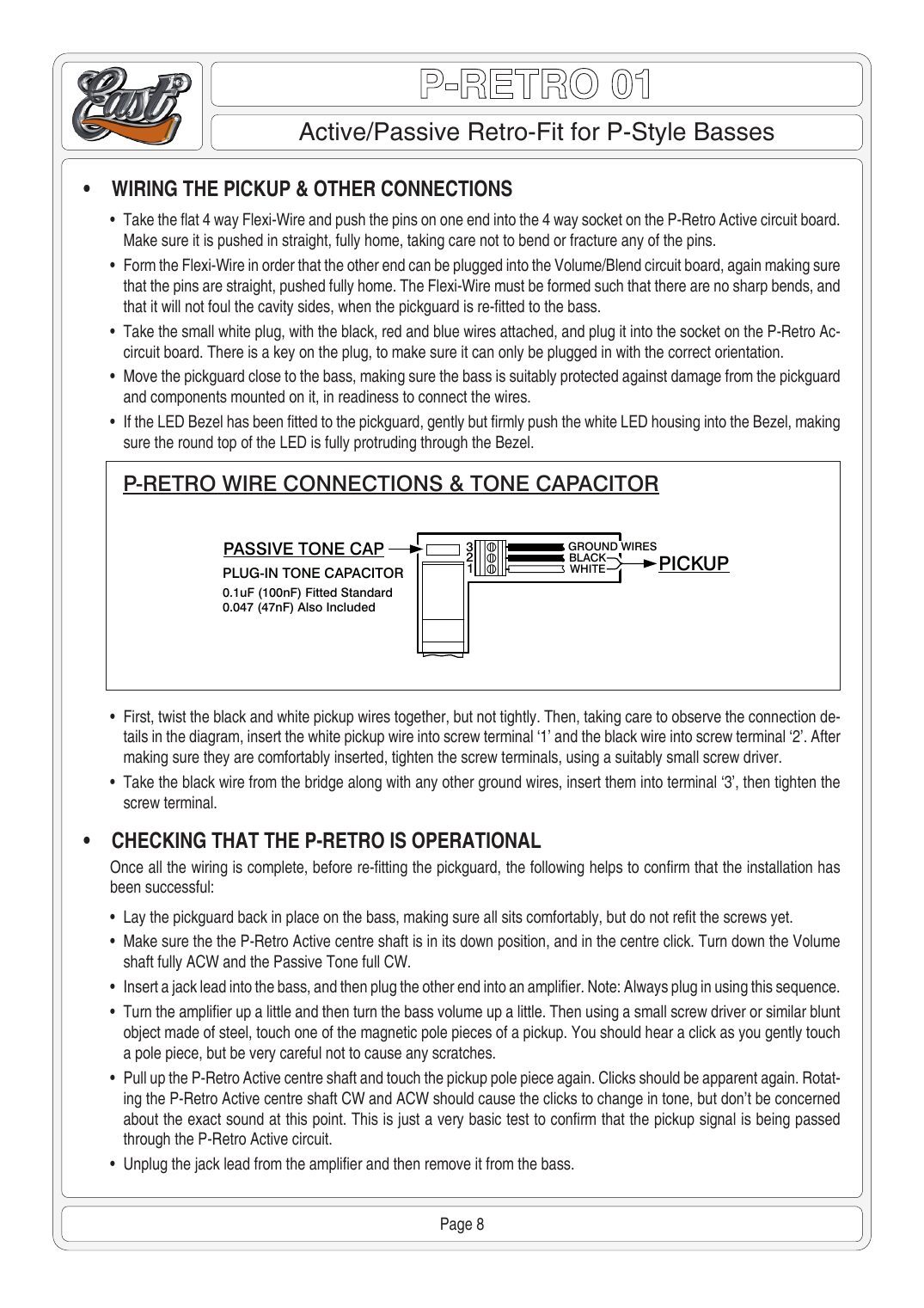
The P-Retro replaces a P-Bass volume and tone with two stacked knobs and needs no soldering: the pickup and ground wires go into three screw terminals on the Volume/Tone board.
You need: P-Retro kit (Active board with jack, Volume/Tone board with Li-Pol battery, 4-way flexi-wire, charger and jack adaptor), small screwdriver, wire strippers.
| # | From | To | Notes |
|---|---|---|---|
| 1 | Pickup: white (hot) | Screw terminal 1 | Twist white and black together loosely first |
| 2 | Pickup: black (cold) | Screw terminal 2 | |
| 3 | Bridge ground wire, plus any other ground wires | Screw terminal 3 | |
| 4 | 4-way flexi-wire | Active board 4-way socket to the Volume/Tone board | Pins straight and fully home; no sharp bends |
| 5 | Small white plug (black, red, blue wires) | Socket on the Active board | Keyed: it only fits one way |
| 6 | Plug-in tone capacitor | Socket beside the screw terminals | 0.1 µF fitted; 0.047 µF also included |
Step by step
- Cut the pickup's white and black wires close to the old volume pot, and any ground wires close to where they were soldered. Strip 6-7 mm.
- Fit the Active board (with the jack) in the middle hole and the Volume/Tone board in the remaining hole, then snip the battery ties.
- Plug the 4-way flexi-wire between the two boards and the small keyed plug into the Active board.
- Put the white pickup wire in terminal 1, black in terminal 2 and the bridge ground in terminal 3, then tighten.
- Test: volume down, tone up, plug in, tap a pole piece in passive and again with the volume pulled up (active). Then charge the battery fully.
- Don't plug the battery pack in while you install it.
Uni-Pre: pickups, battery, jack and the ground star point
The Uni-Pre's Volume/Blend board takes all the outside wiring on screw terminals. The board ships connected to the EQ board; you plug in the Mid control, then connect the pickups, battery and jack. This is the same on the 3-, 4- and 5-knob versions.
You need: Uni-Pre system, 9 V battery, output jack (John East's drawing uses a switched jack), adhesive copper foil, hookup wire.
| # | From | To | Notes |
|---|---|---|---|
| 1 | Bridge pickup: hot | Pickup inputs: BRIDGE HOT screw terminal | |
| 2 | Bridge pickup: cold or ground | Pickup inputs: BRIDGE COLD/GND | |
| 3 | Neck pickup: hot | Pickup inputs: NECK HOT | |
| 4 | Neck pickup: cold or ground | Pickup inputs: NECK COLD/GND | |
| 5 | Power & output terminal: red | Battery clip red (+) | |
| 6 | Power & output terminal: black | Output jack: the switching (ring) tag, as drawn | Battery − is switched at the jack: power comes on when a mono jack is plugged in |
| 7 | Power & output terminal: orange (OUTPUT) | Output jack: tip/hot tag | |
| 8 | Power & output terminal: green | Output jack: ground tag | |
| 9 | Output jack: ground tag | Copper foil star point (second green wire) | Main ground point |
| 10 | Bridge ground, cavity screens | Close to the star point | |
| 11 | 7-way lead (brown to purple) | EQ board | Plug-in; already connected when shipped |
| 12 | 5-way lead (yellow to grey) | Active/passive toggle (3-knob) or passive tone push/pull (4- and 5-knob) | Plug-in |
Step by step
- Before installing, connect one pickup, snap on a battery and plug into an amp to check the preamp works out of the box.
- Check the layout fits: 7 mm holes for single pots, 9 mm for dual (stacked) pots; spacer rings are supplied for larger holes.
- Line the cavity face the pots mount against with adhesive copper foil. Don't rely on conductive paint to ground the pots.
- Connect the bridge and neck pickups' hot and cold to the pickup input screw terminals.
- Connect red to the battery, and black, orange and green to the output jack as drawn.
- Solder the second green wire from the jack's ground tag to the copper foil (the star point), and the bridge and cavity grounds near it.
- Plug in the Mid control, then set the gain trims and EQ jumpers.
- FUNCTION-LEVEL for the jack: John East draws the jack from underneath; follow the drawing for which tag each coloured wire goes to.
FAQ
Why does a John East preamp need a stereo jack?
The battery's black wire goes to the jack's ring. A normal mono lead joins ring to sleeve when it's plugged in, which turns the preamp on. Unplug when you're done, or the battery stays connected.
What does the pickups switch on a J-Retro do?
It must point toward the jack for the blend knob to work. In active mode the other position gives a passive equal mix of both pickups; in passive mode the two positions give the bridge pickup alone or both pickups.
Will a J-Retro 01 fit my Jazz Bass?
It's made to drop into a standard J control plate cavity, battery included, but cavities vary. Check the slot is wide enough for a PP3 (9 V) battery and ideally 32.5 mm deep before you solder anything.
How do I set the J-Retro or U-Retro gain presets?
They ship at minimum, which suits most medium and high output pickups. If the output is low, turn the blend to the neck pickup, raise its preset, then turn to the bridge pickup and match its preset to the neck.
Can John East modules run on 18 volts?
The BTB-01, BTBM-01, Mid Sweep 01, MPB-01 and the MMSR preamps all run on 9 to 18 volts DC.
Is the P-Retro reversible?
Yes. It fits with screw terminals and no soldering, so you can return the bass to stock. Its internal Li-Pol battery charges through the jack and gives up to 40 hours per charge.
What's different about the MMSR Stingray-style EQ?
Like the original Music Man 2-band EQ it isn't flat with the knobs at halfway: treble is +20/−16 dB at 10 kHz and bass +14/−7 dB at 40 Hz, with more boost than cut.
Related
- John East bass preamps
- John East J-Tone 01 preamp
- All bass wiring diagrams
- Bartolini bass wiring diagrams
- Seymour Duncan bass wiring diagrams
- EMG bass wiring diagrams
- DiMarzio bass wiring diagrams
Questions about a hookup? Call 877-839-3531 or email sales@bestbassgear.com.